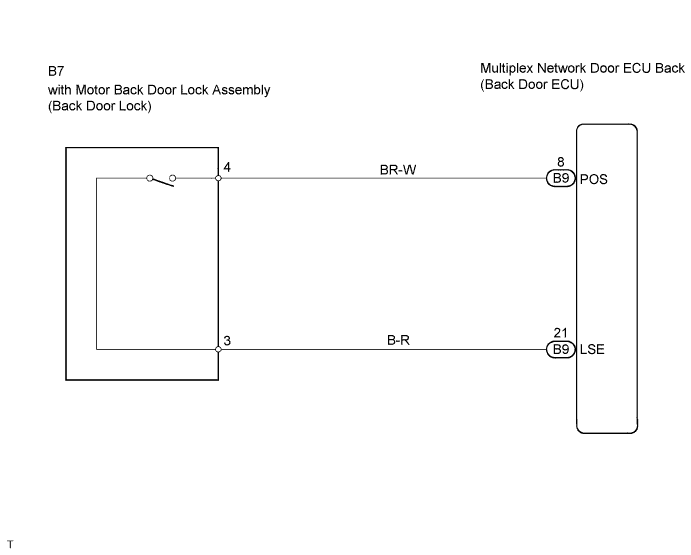
DTC B2215 Back Door Closer Switch Malfunction |
| DTC No. | DTC Detection Condition | Trouble Area |
| B2215 | Back door does not operate |
|
| 1.CHECK HARNESS AND CONNECTOR (MULTIPLEX NETWORK DOOR ECU - W/MOTOR BACK DOOR LOCK ASSEMBLY) |
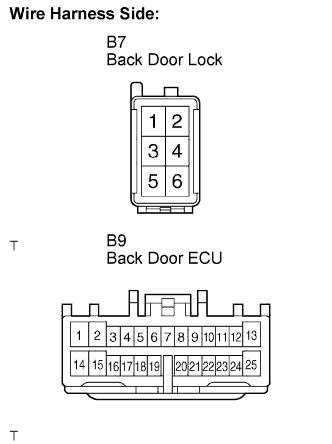 |
Disconnect the B7 back door lock and B9 back door ECU connectors.
Check the continuity between the terminals of the back door lock (B7) and back door ECU (B9) connectors.
| Symbols (Terminal No.) | Specified Condition |
| - (B7-4) - POS (B9-8) | Continuity |
| - (B7-3) - LSE (B9-21) |
|
| ||||
| OK | |
 |
| 2.INSPECT WITH MOTOR BACK DOOR LOCK ASSEMBLY |
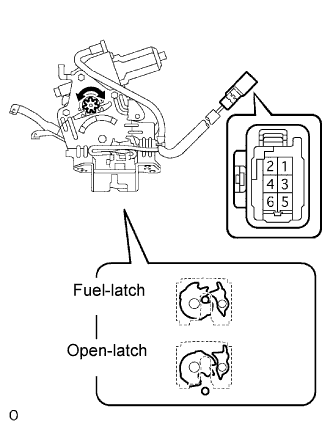 |
Check operation of the door lock.
Using a screwdriver, push the latch in order to put the back door lock in the locked condition (full-latch position).
Connect the positive (+) lead to terminal 1 and the negative (-) lead to terminal 2. Then, check operation of the latch.
Inspect motor operation when battery voltage is applied to the terminals.
| Measurement Condition | Specified Condition |
| Battery positive (+) - Terminal 2 Battery negative (-) - Terminal 1 | Clockwise (Motor in normal rotation) |
| Battery positive (+) - Terminal 1 Battery negative (-) - Terminal 2 | Counterclockwise (Motor in reverse rotation) |
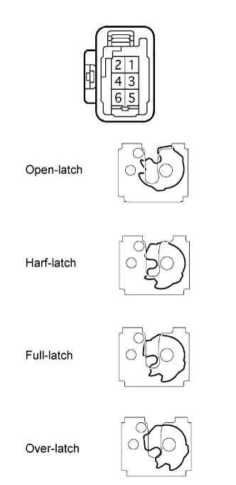 |
Check the back door courtesy switch continuity.
Check the continuity between the terminals of the courtesy switch.
| Door Lock Latch Position | Terminal No. | Specified Condition |
| Open-latch position, Half-latch position | 4 - 5 | Continuity |
| Full-latch position, Over-latch position | 4 - 5 | No continuity |
Check the back door latch switch continuity.
Check the continuity between the terminals of the latch switch.
| Door Lock Latch Position | Terminal No. | Specified Condition |
| Open-latch position, Over-latch position | 4 - 6 | Continuity |
| Half-latch position, Full-latch position | 4 - 6 | No continuity |
Check the position switch continuity.
Connect the battery positive (+) lead to connector terminal 1 and the negative (-) lead to connector terminal 2.
| Door Lock Latch Position | Terminal No. | Specified Condition |
| Any position other than motor stop position (Motor in operation) | 3 - 4 | Continuity |
| Motor stop position (Gear in original position) | 3 - 4 | No continuity |
|
| ||||
| OK | ||
 | ||
| ||
