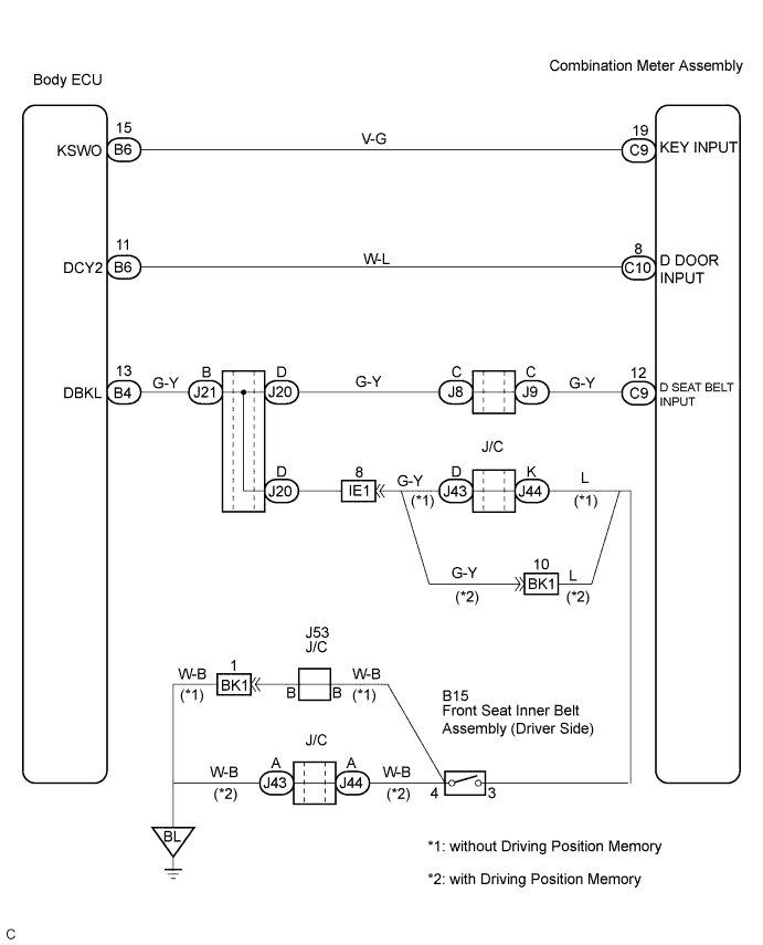
METER / GAUGE SYSTEM > Warning Buzzer does not Sound |
| 1.CHECK BUZZER |
Check that all of the warning buzzers sound.
| Result | Proceed to |
| All warning buzzers do not sound | A |
| Key reminder warning buzzer does not sound | B |
| Seat belt warning buzzer does not sound | C |
|
| ||||
|
| ||||
| A | ||
 | ||
| ||
| 2.INSPECT COMBINATION METER ASSEMBLY |
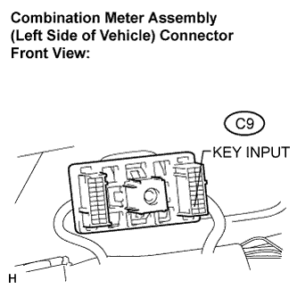 |
Disconnect the C9 connector.
Measure the voltage according to the value(s) in the table below.
| Tester Connection | Condition | Specified Condition |
| C9-19 (KEY INPUT) - Body ground | Key is inserted | Below 1 V |
| C9-19 (KEY INPUT) - Body ground | Key is not inserted | 10 to 14 V |
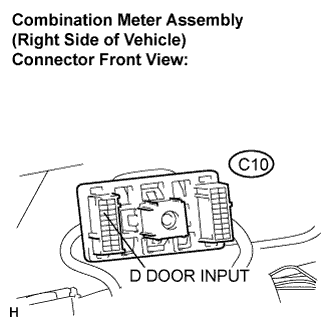 |
Disconnect the C10 connector.
Measure the voltage according to the value(s) in the table below.
| Tester Connection | Condition | Specified Condition |
| C10-8 (D DOOR INPUT) - Body ground | Door is open | Below 1 V |
| C10-8 (D DOOR INPUT) - Body ground | Door is closed | 10 to 14 V |
|
| ||||
| OK | ||
| ||
| ||
| 3.CHECK HARNESS AND CONNECTOR (COMBINATION METER - MULTIPLEX NETWORK BODY ECU) |
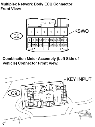 |
Disconnect the B6 and C9 connectors.
Measure the resistance according to the value(s) in the table below.
| Tester Connection | Condition | Specified Condition |
| B6-15 (KSWO) - C9-19 (KEY INPUT) | Always | Below 1 Ω |
| B6-15 (KSWO) - Body ground | Always | 10 kΩ or higher |
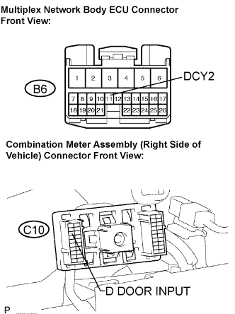 |
Disconnect the B6 and C10 connectors.
Measure the resistance according to the value(s) in the table below.
| Tester Connection | Condition | Specified Condition |
| B6-11 (DCY2) - C10-8 (D DOOR INPUT) | Always | Below 1 Ω |
| B6-11 (DCY2) - Body ground | Always | 10 kΩ or higher |
|
| ||||
| OK | ||
| ||
| ||
| 4.INSPECT COMBINATION METER ASSEMBLY |
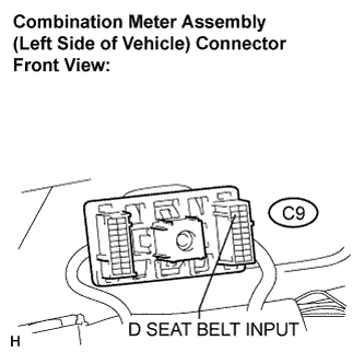 |
Disconnect the C9 connector.
Measure the resistance according to the value(s) in the table below.
| Tester Connection | Condition | Specified Condition |
| C9-12 (D SEAT BELT INPUT) - Body ground | Seat belt is unfastened | Below 1 Ω |
| C9-12 (D SEAT BELT INPUT) - Body ground | Seat belt is fastened | 10 kΩ or higher |
|
| ||||
| OK | ||
| ||
| ||
| 5.INSPECT FRONT SEAT INNER BELT ASSEMBLY LH |
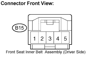 |
Disconnect the B12 connector.
Measure the resistance according to the value(s) in the table below.
| Tester Connection | Condition | Specified Condition |
| B15-3 - B15-4 | Seat belt is unfastened | Below 1 Ω |
| B15-3 - B15-4 | Seat belt is fastened | 10 kΩ or higher |
|
| ||||
| OK | ||
| ||
| ||

