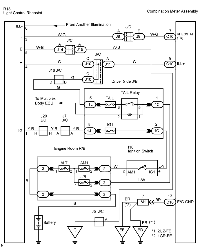
METER / GAUGE SYSTEM > Operating Light Control Rheostat does not Change Light Brightness |
| 1.CHECK TAILLIGHT |
Check that the tail light comes on when the ignition switch is turned to the ON position and light control switch is in the TAIL or HEAD position.
|
| ||||
| OK | |
 |
| 2.CHECK ILLUMINATION |
Check that the illumination of the radio and player, center cluster module switch, etc. can be adjusted by the light control rheostat switch.
|
| ||||
| OK | |
|
| 3.INSPECT COMBINATION METER ASSEMBLY |
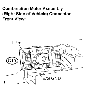 |
Disconnect the C10 connector.
Measure the voltage according to the value(s) in the table below.
| Tester connection | Condition | Specified condition |
| C10-9 - Body ground | Ignition switch ON and light control switch TAIL or HEAD | 10 to 14 V |
Measure the resistance according to the value(s) in the table below.
| Tester connection | Condition | Specified condition |
| C10-13 - Body ground | Always | Below 1 Ω |
|
| ||||
| OK | |
|
| 4.CHECK HARNESS AND CONNECTOR (LIGHT CONTROL RHEOSTAT - COMBINATION METER) |
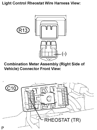 |
Disconnect the R13 and C10 connectors.
Measure the resistance according to the value(s) in the table below.
| Tester connection | Condition | Specified condition |
| R13-3 (-) - C10-7 (RHEOSTAT (TR)) | Always | Below 1 Ω |
| R13-3 (-) - Body ground | Always | 10 kΩ or higher |
|
| ||||
| OK | |
|
| 5.INSPECT LIGHT CONTROL RHEOSTAT |
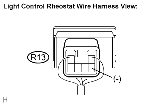 |
Remove the light control rheostat with connector still connected.
 |
Measure the voltage according to the value(s) in the table below.
| Tester connection | Condition | Specified condition |
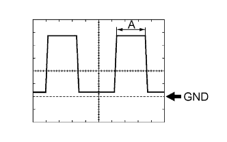
| R13-3 (-) - Body ground | Light control rheostat is turned volume up → volume down | Pulse generation (See waveform 1) |
| Item | Condition |
| Tool setting | 2 V/DIV., 1 ms./DIV. |
| Vehicle condition | Ignition switch ON and light control switch TAIL or HEAD |
|
| ||||
| OK | ||
 | ||
| ||
| 6.INSPECT LIGHT CONTROL RHEOSTAT (POWER SOURCE) |
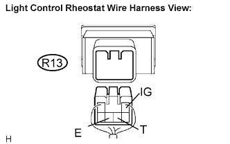 |
Disconnect the R13 connector.
Measure the voltage according to the value(s) in the table below.
| Tester connection | Condition | Specified condition |
| R13-1 (IG) - Body ground | Ignition switch ON | 10 to 14 V |
| R13-4 (T) - Body ground | Light control switch TAIL or HEAD | 10 to 14 V |
Measure the resistance according to the value(s) in the table below.
| Tester connection | Condition | Specified condition |
| R13-5 (E) - Body ground | Always | Below 1 Ω |
|
| ||||
| OK | ||
| ||
| ||

