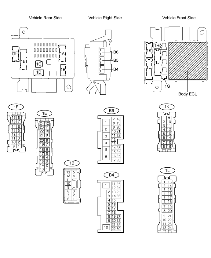
POWER DOOR LOCK CONTROL SYSTEM > TERMINALS OF ECU |
| CHECK INSTRUMENT PANEL JUNCTION BLOCK ASSEMBLY (BODY ECU) |
Disconnect the 1B, 1E, 1F, 1H, 1K, 1L, B4 and B6 J/B connectors, and check the voltage or continuity of each terminal of the vehicle side connectors.
| Symbols (Terminal No.) | Wiring Color | Condition | Specified Condition |
| BDR1 (1E-9) - Body Ground | G-W - Body ground | Always | 10 to 14 V |
| BECU (1B-4) - Body Ground | W-R - Body ground | Always | 10 to 14 V |
| BECU (1F-12) - Body Ground | |||
| BECU (1L-4) - Body Ground | |||
| GND1 or GND2 (1H-2) - Body Ground | W-B - Body ground | Always | Below 1 Ω |
| KSW (B6-14) - Body Ground | G-Y - Body ground | No key inserted in ignition key cylinder → Key inserted | 10 kΩ or higher → Below 1 Ω |
| L1(1K-5) - Body Ground | L-W - Body ground | Door control switch (Master switch) OFF → LOCK | 10 kΩ or higher → Below 1 Ω |
| UL1 (1K-1) - Body Ground | L-O - Body ground | Door control switch (Master switch) OFF → UNLOCK | 10 kΩ or higher → Below 1 Ω |
| L2 (1K-3) - Body Ground | L - Body ground | Driver side door key cylinder OFF → LOCK | 10 kΩ or higher → Below 1 Ω |
| UL3 (B4-12) - Body Ground | G - Body ground | Driver side door key cylinder OFF → UNLOCK twice (within 3 sec.) | 10 kΩ or higher → Below 1 Ω |
Reconnect the J/B connectors 1B, 1E, 1F, 1H, 1K, 1L, B4 and B6, and check the voltage of each terminal of the connectors.
| Symbols (Terminal No.) | Wiring Color | Condition | Specified Condition |
| DCTY (B5-23) - Body Ground | R-B - Body ground | Driver door CLOSED → OPEN | 10 to 14 V → Below 1 V |
| ACT+ (1L-9) - Body Ground | L-R - Body ground | Door control switch (master switch or passenger side switch) or driver door key cylinder OFF → LOCK | Below 1 V → 10 to 14 V → Below 1 V |
| ACT+ (1L-6) - Body Ground | L-R - Body ground | ||
| ACT+ (1L-11) - Body Ground | L-R - Body ground | ||
| ACT+ (1L-10) - Body Ground | L-R - Body ground | ||
| ACT- (1L-18) - Body Ground | L-B - Body ground | Door control switch (master switch or passenger side switch) or driver door key cylinder OFF → LOCK | Below 1 V → 10 to 14 V → Below 1 V |
| ACT- (1L-23) - Body Ground | L-B - Body ground | ||
| ACT- (1L-22) - Body Ground | L-B - Body ground | ||
| ACTD (B4-10) - Body Ground | L-B - Body ground | Driver side door key cylinder OFF → 2-step unlocking | Below 1 V → 10 to 14 V → Below 1 V |
| LSWD (B4-21) - Body Ground | W-R - Body ground | Driver side door UNLOCK → LOCK | 10 to 14 V → Below 1 V |
| LSWP (B4-30) - Body Ground | B-W - Body ground | Passenger side door UNLOCK → LOCK | 10 to 14 V → Below 1 V |
| LSR (1L-16) - Body Ground | W - Body ground | Rear left door UNLOCK → LOCK | 10 to 14 V → Below 1 V |
| LSR (1K-15) - Body Ground | W - Body ground | Rear right door UNLOCK → LOCK | 10 to 14 V → Below 1 V |
| CHECK MULTIPLEX NETWORK DOOR ECU BACK (BACK DOOR ECU) |

Disconnect the B8 and B9 ECU connectors, and check the voltage or continuity of each terminal of the wire harness side connectors.
| Symbols (Terminal No.) | Wiring Color | Condition | Specified Condition |
| BDR (B8-4) - Body Ground | L - Body ground | Always | 10 to 14 V |
| BECU (B8-5) - Body Ground | L-R - Body ground | Always | 10 to 14 V |
| GND (B8-3) - Body Ground | W-B - Body ground | Always | Below 1 Ω |
| SIG (B8-6) - Body Ground | B - Body ground | No key inserted in ignition key cylinder → Key inserted | 10 k Ω or higher → Below 1 Ω |
| HSW+ (B9-10) - Body Ground | V - W - Body ground | Back door opener switch OFF → ON | 10 k Ω or higher → Below 1 Ω |
| HSW- (B9-22) - Body Ground | LG-R - Body ground | ||
| HALF (B9-6) - Body Ground | R-G - Body ground | Back door OPEN → CLOSED | 10 k Ω or higher → Below 1 Ω |
| LSE (B9-21) - Body Ground | B-R - Body ground | Always | Always |
Reconnect the connectors, and check the voltage of each terminal of the connectors.
| Symbols (Terminal No.) | Wiring Color | Condition | Specified Condition |
| ACT+ (B9-15) - Body Ground | L-B - Body ground | Back door OPEN → NOT COMPLETELY CLOSED → Motor in normal rotation (Right turn) → Motor in revers rotation (Left turn) → Operation completed (Back door CLOSED) | Below 1 V → Below 1 V → 10 to 14 V → Below 1 V → Below 1 V |
| ACT- (B9-14) - Body Ground | L-R - Body ground | Back door OPEN → NOT COMPLETELY CLOSED → Motor in normal rotation (Right turn) → Motor in revers rotation (Left turn) → Operation completed (Back door CLOSED) | Below 1 V → Below 1 V → Below 1 V → 10 to 14 V → Below 1 V |
| FULL (B9-7) - Body Ground | G-Y - Body ground | Back door CLOSED → OPEN | 10 to 14 V → Below 1 V |
| POS (B9-8) - Body Ground | BR-W - Body ground | Back door OPEN → Closer in operation → CLOSED | Below 1 V 10 to 14 V → Below 1 V |