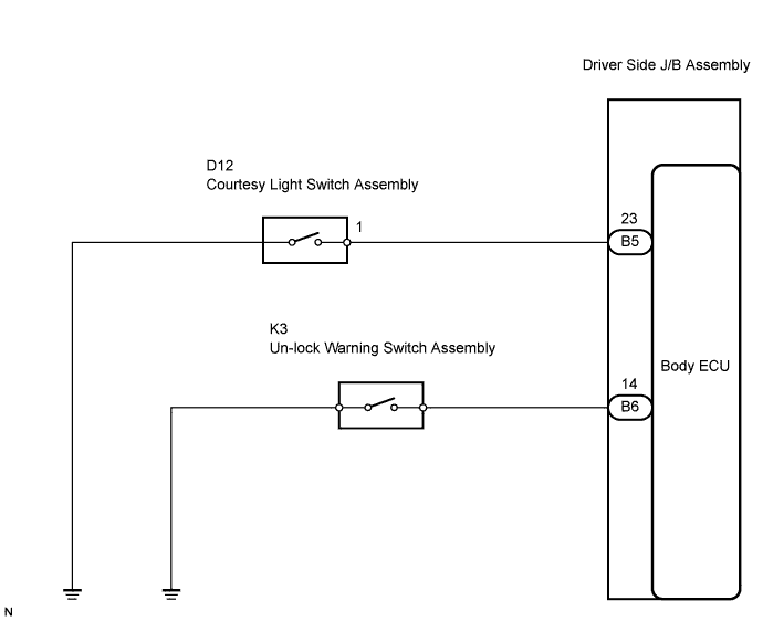
POWER DOOR LOCK CONTROL SYSTEM > Key Lock-in Prevention Function does not Work Properly (Manual Operation and Operation Interlocked with Key are Active) |
| 1.READ VALUE OF INTELLIGENT TESTER |
Using the intelligent tester, check that the un-lock warning switch signal is output when the switch is operated.
| Item | Measurement Item/ Display (Range) | Normal Condition | Diagnostic Note |
| KEY UNLK WRN SW | Key un-lock warning SW signal/ON or OFF | ON: Key is in ignition key cylinder OFF: Key is not in ignition key cylinder | - |
|
| ||||
| NG | |
 |
| 2.INSPECT UN-LOCK WARNING SWITCH ASSEMBLY |
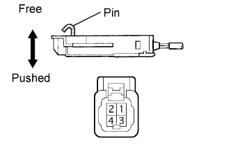 |
Remove the un-lock warning switch.
Inspect the un-lock warning switch continuity.
| Terminal No. | Condition | Specified Condition |
| 1 - 2 | Free | 10 kΩ or higher |
| Pushed | Below 1 Ω |
|
| ||||
| OK | |
|
| 3.CHECK HARNESS AND CONNECTOR (UN-LOCK WARNING SWITCH - BODY ECU) |
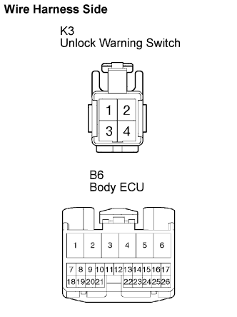 |
Disconnect the K3 un-lock warning switch and B12 body ECU connectors.
Check the continuity between the terminals of the un-lock warning switch (K3) and body ECU (B6) connectors.
| Symbols (Terminal No.) | Specified Condition |
| (K3-2) - KSW (B6-14) | Below 1 Ω |
| (K3-1) - Body ground | Below 1 Ω |
|
| ||||
| OK | ||
 | ||
| ||
| 4.READ VALUE OF INTELLIGENT TESTER |
Using the intelligent tester, check that the driver door courtesy switch signal is output when the switch is operated.
| Item | Measurement Item/ Display (Range) | Normal Condition | Diagnostic Note |
| D DOR CTY SW | Driver door courtesy SW signal / ON or OFF | ON: Driver door is open OFF: Driver door is closed | - |
|
| ||||
| NG | |
|
| 5.INSPECT COURTESY LIGHT SWITCH |
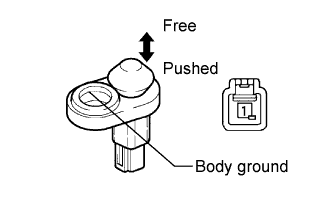 |
Remove the courtesy light switch.
Inspect the courtesy light switch continuity.
| Terminal No. | Condition | Specified Condition |
| 1 - Body ground | Free | Below 1 Ω |
| Pushed | 10 kΩ or higher |
|
| ||||
| OK | |
|
| 6.CHECK HARNESS AND CONNECTOR (COURTESY LIGHT SWITCH - BODY ECU) |
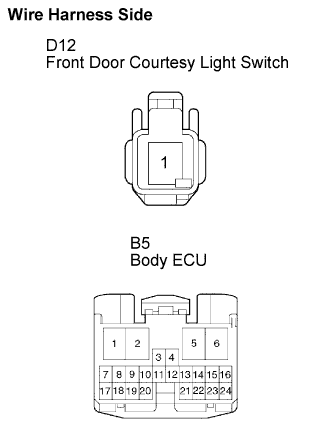 |
Disconnect the courtesy light switch and body ECU connectors.
Check the continuity between the terminals of the courtesy light switch (D12) and body ECU (B5) connectors.
| Symbols (Terminal No.) | Specified Condition |
| (D12-1) - DCTY (B5-23) | Below 1 Ω |
|
| ||||
| OK | ||
| ||
| ||

