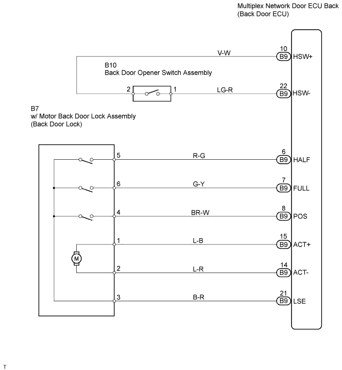
POWER DOOR LOCK CONTROL SYSTEM > Only Back Door cannot be Opened |
| 1.READ VALUE OF INTELLIGENT TESTER |
Check the data list of back door opener switch.
| Item | Measurement Item/ Display (Range) | Normal Condition | Diagnostic Note |
| DOOR HANDLE SW | Back door opener SW signal / ON or OFF | ON: Back door opener is pushed OFF: Back door opener is not pushed | - |
|
| ||||
| NG | |
 |
| 2.INSPECT BACK DOOR OPENER SWITCH ASSEMBLY |
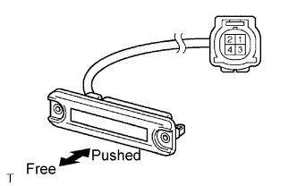 |
Remove the back door opener switch.
Inspect the back door opener switch continuity.
| Terminal No. | Condition | Specified Condition |
| 1 - 2 | Free | 10 kΩ or higher |
| Pushed | Below 1 Ω |
|
| ||||
| OK | |
|
| 3.CHECK HARNESS AND CONNECTOR (BACK DOOR OPENER SWITCH - BACK BODY) |
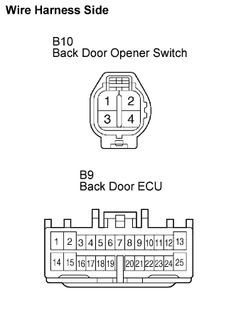 |
Disconnect the B10 back door opener switch and B9 back door ECU connectors.
Check the continuity between the terminals of the back door opener switch (B10) and back door ECU (B9) connectors.
| Symbols (Terminal No.) | Specified Condition |
| (B10-1) - HSW- (B9-22) | Below 1 Ω |
| (B10-2) - HSW+ (B9-10) | Below 1 Ω |
|
| ||||
| OK | |
|
| 4.PERFORM ACTIVE TEST BY INTELLIGENT TESTER |
Select the active test, and then check that the power door lock operates.
| Item | Test Details | Diagnostic Note |
| DOOR LOCK | Drive the door lock motor at all doors LOCK/OFF | - |
| DOOR LOCK | Drive the door lock motor at all doors UNLOCK/ OFF | - |
|
| ||||
| NG | |
|
| 5.INSPECT W/MOTOR BACK DOOR LOCK ASSEMBLY |
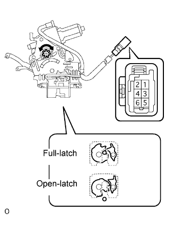 |
Check operation of the door lock.
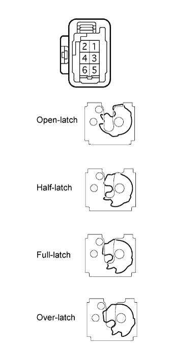
Using a screwdriver, push the latch in order to put the back door lock in the locked condition (full-latch position).
Connect the positive (+) lead to terminal 1 and the negative (-) lead to terminal 2. Then, check operation of the latch.
Inspect motor operation when battery voltage is applied to the terminals.
| Measurement Condition | Specified Condition |
| Battery positive (+) → Terminal 2 Battery negative (-) → Terminal 1 | Clockwise (Motor in normal rotation) |
| Battery positive (+) → Terminal 1 Battery negative (-) → Terminal 2 | Counterclockwise (Motor in reverse rotation) |
 |
Check the back door courtesy switch continuity.
Check the continuity between the terminals of the courtesy switch.
| Door Lock Latch Position | Terminal No. | Specified Condition |
| Open-latch position, Half-latch position | 4 - 5 | Below 1 Ω |
| Full-latch position, Over-latch position | 4 - 5 | 10 kΩ or higher |
Check the back door latch switch continuity.
Check the continuity between the terminals of the latch switch.
| Door Lock Latch Position | Terminal No. | Specified Condition |
| Open-latch position, Over-latch position | 4 - 6 | Below 1 Ω |
| Half-latch position, Full-latch position | 4 - 6 | 10 kΩ or higher |
Check the position switch continuity.
Connect the battery positive (+) lead to connector terminal 1 and the negative (-) lead to connector terminal 2.
| Door Lock Latch Position | Terminal No. | Specified Condition |
| Any position other than motor stop position (Motor in operation) | 3 - 4 | Below 1 Ω |
| Motor stop position (Gear in original position) | 3 - 4 | 10 kΩ or higher |
|
| ||||
| OK | ||
 | ||
| ||

