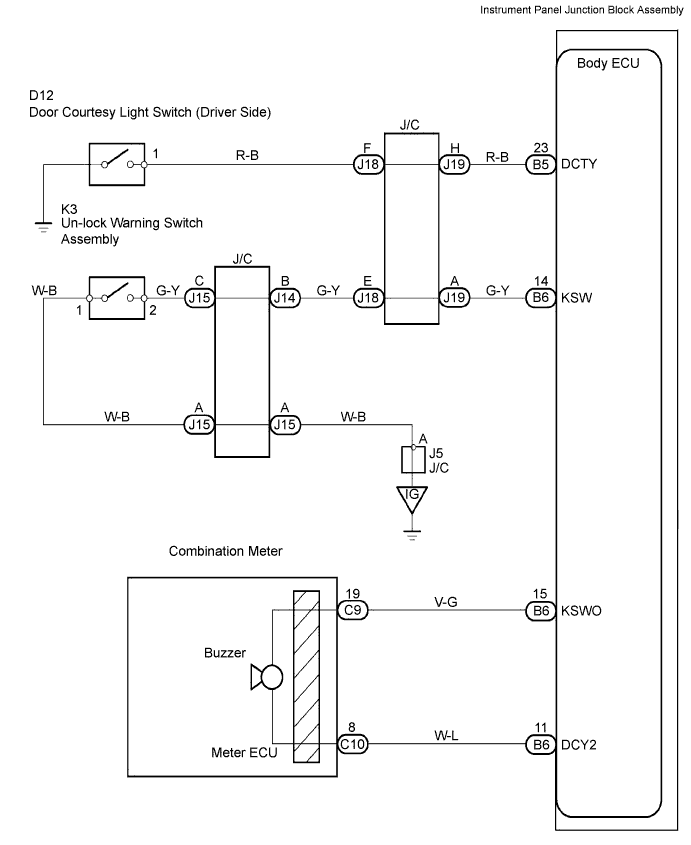
KEY REMINDER WARNING SYSTEM > Key Reminder Buzzer does not Sound |
| 1.READ VALUE OF INTELLIGENT TESTER (COURTESY LIGHT SWITCH) |
Connect the intelligent tester to the DLC3.
Turn the ignition switch ON and push the intelligent tester main switch ON.
Select the item "D DOR CTY SW" in the DATA LIST and read its value displayed on the intelligent tester.
|
| ||||
| NG | |
 |
| 2.INSPECT COURTESY LIGHT SWITCH (DRIVER SIDE) |
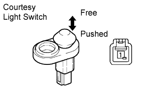 |
Remove the courtesy light switch.
Measure the resistance according to the value(s) table below.
| Terminal No. | Condition | Specified Condition |
| 1 - Body ground | Switch Free | Below 1 Ω |
| Switch Pushed | 10 kΩ or higher |
|
| ||||
| OK | |
|
| 3.CHECK HARNESS AND CONNECTOR (BODY ECU - COURTESY LIGHT SWITCH) |
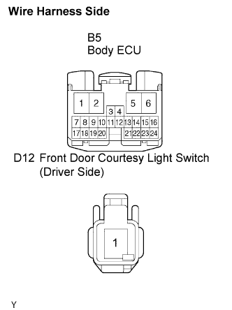 |
Disconnect the D12 door courtesy light switch (driver side) and B5 ECU connectors.
Measure the resistance according to the value(s) table below.
| Symbols (Terminal No.) | Specified Condition |
| DCTY (B5-23) - (D12-1) | Below 1 Ω |
|
| ||||
| OK | |
|
| 4.CHECK BUZZER (COMBINATION METER) |
Check buzzer (combination meter). (Click here)
|
| ||||
| OK | |
|
| 5.READ VALUE OF INTELLIGENT TESTER (KEY UN-LOCK WARNING SWITCH) |
Connect the intelligent tester to the DLC3.
Turn the ignition switch ON and push the intelligent tester main switch ON.
Select the item "KEY UNLK WRN SW" in the DATA LIST and read its value displayed on the intelligent tester.
|
| ||||
| NG | |
|
| 6.INSPECT UN-LOCK WARNING SWITCH ASSEMBLY |
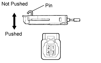 |
Remove the un-lock warning switch.
Measure the resistance according to the value(s) table below.
| Terminal No. | Condition | Specified Condition |
| 1 - 2 | Free | 10 kΩ or higher |
| 1 - 2 | Pushed | Below 1 Ω |
|
| ||||
| OK | |
|
| 7.CHECK HARNESS AND CONNECTOR (BODY ECU - UN-LOCK WARNING SWITCH) |
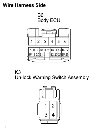 |
Disconnect the B6 ECU connector.
Disconnect the K3 warning switch connector.
Measure the resistance according to the value(s) table below.
| Symbols (Terminal No.) | Specified Condition |
| KSW (B6-14) - (K3-2) | Below 1 Ω |
| K3-1 - Body ground | Below 1 Ω |
|
| ||||
| OK | ||
 | ||
| ||
| 1.CHECK COURTESY LIGHT SWITCH |
Put the dome light assembly No. 2 switch in the door position and open the driver side door. Then check that the courtesy light switch comes on.
|
| ||||
| NG | |
|
| 2.INSPECT COURTESY LIGHT SWITCH |
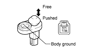 |
Remove the courtesy light switch.
Measure the resistance according to the value(s) table below.
| Terminal No. | Condition | Specified Condition |
| 1 - Body ground | Free | Below 1 Ω |
| Pushed | 10 kΩ or higher |
|
| ||||
| OK | |
|
| 3.CHECK HARNESS AND CONNECTOR (BODY ECU - COURTESY LIGHT SWITCH) |
|
Disconnect the D12 door courtesy light switch (driver side) and B5 ECU connectors.
Measure the resistance according to the value(s) table below.
| Symbols (Terminal No.) | Specified Condition |
| DCTY (B5-23) - (D12-1) | Below 1 Ω |
|
| ||||
| OK | |
|
| 4.CHECK BUZZER (COMBINATION METER) |
Check buzzer (combination meter). (Click here)
|
| ||||
| OK | |
|
| 5.INSPECT UN-LOCK WARNING SWITCH ASSEMBLY |
|
Remove the un-lock warning switch.
Measure the resistance according to the value(s) table below.
| Terminal No. | Condition | Specified Condition |
| 1 - 2 | Free | 10 kΩ or higher |
| Pushed | Below 1 Ω |
|
| ||||
| OK | |
|
| 6.CHECK HARNESS AND CONNECTOR (BODY ECU - UN-LOCK WARNING SWITCH) |
|
Disconnect the B6 ECU connectors.
Disconnect the K3 warning switch connector.
Measure the resistance according to the value(s) table below.
| Symbols (Terminal No.) | Specified Condition |
| KSW (B6-14) - (K3-2) | Below 1 Ω |
| K3-1 - Body ground | Below 1 Ω |
|
| ||||
| OK | ||
| ||
| ||

