Home › BODY ELECTRICAL › DOOR LOCK › BACK DOOR LOCK

BACK DOOR LOCK > INSPECTION

for Preparation Click here


1. INSPECT W/MOTOR BACK DOOR LOCK ASSEMBLY


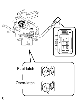
    B065423E01
  1. Check operation of the door lock.

    1. Using a screwdriver, push the latch in order to put the back door lock in the locked condition (full-latch position).

    2. Connect the positive (+) lead to terminal 1 and the negative (-) lead to terminal 2. Then, check operation of the latch.

      Standard:
      The latch turns to the open-latch position

    3. Inspect motor operation when battery voltage is applied to the terminals.

      OK:
      Measurement Condition
      Specified Condition
      Battery positive (+) → Terminal 2
      Battery negative (-) → Terminal 1
      Clockwise (Motor in normal rotation)
      Battery positive (+) → Terminal 1
      Battery negative (-) → Terminal 2
      Counterclockwise (Motor in reverse rotation)
      If the operation is not as specified, replace the door lock assembly.


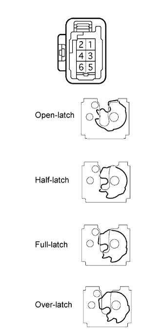
    B062719E01
  1. Check the back door courtesy switch continuity.

    1. Measure the resistance according to the value(s) in the table below.

      Standard resistance:
      Door Lock Latch Position
      Terminal No.
      Specified Condition
      Open-latch position,
      Half-latch position
      4 - 5
      Below 1 Ω
      Full-latch position,
      Over-latch position
      4 - 5
      10 kΩ or higher

      If the continuity is not as specified, replace the door lock assembly.

  1. Check the back door latch switch continuity.

    1. Measure the resistance according to the value(s) in the table below.

      Standard resistance:
      Door Lock Latch Position
      Terminal No.
      Specified Condition
      Open-latch position,
      Over-latch position
      4 - 6
      Below 1 Ω
      Half-latch position,
      Full-latch position
      4 - 6
      10 kΩ or higher

      If the continuity is not as specified, replace the door lock assembly.

  1. Check the position switch continuity.

    1. Connect the battery positive (+) lead to connector terminal 1 and the negative (-) lead to connector terminal 2.

      Standard resistance:
      Door Lock Latch Position
      Terminal No.
      Specified Condition
      Any position other than motor stop position
      (Motor in operation)
      3 - 4
      Below 1 Ω
      Motor stop position
      (Gear in original position)
      3 - 4
      10 kΩ or higher

      If the continuity is not as specified, replace the door lock assembly.