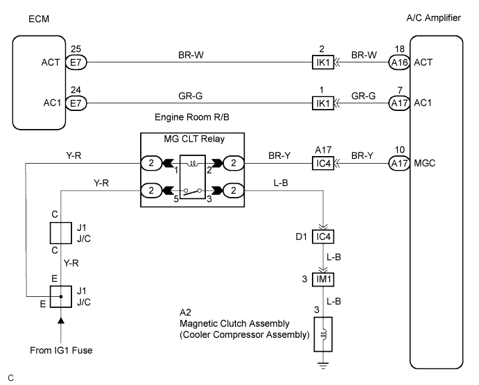
AIR CONDITIONING SYSTEM > Compressor Circuit |
| 1.READ VALUE OF INTELLIGENT TESTER |
Connect the intelligent tester to the DLC3.
Turn the ignition switch ON and push the intelligent tester main switch on.
Check the A/C magnetic clutch input signal using DATA LIST.
| Item | Measurement Item/ Display (Range) | Normal Condition | Diagnostic Note |
| A/C SIG | A/C signal / ON or OFF | A/C switch pushed: ON A/C switch released: OFF | - |
|
| ||||
| OK | |
 |
| 2.READ VALUE OF INTELLIGENT TESTER |
Connect the intelligent tester to the DLC3.
Turn the ignition switch ON and push the intelligent tester main switch on.
Check the A/C magnetic clutch operation permission signal using DATA LIST.
| Item | Measurement Item/ Display (Range) | Normal Condition | Diagnostic Note |
| A/C MAG CLUTCH | A/C magnetic clutch / ON or OFF | A/C switch ON: ON A/C switch OFF: OFF | - |
|
| ||||
| OK | |
|
| 3.PERFORM ACTIVE TEST BY INTELLIGENT TESTER |
Connect the intelligent tester to the DLC3.
Turn the ignition switch ON and push the intelligent tester main switch on.
Check the A/C magnetic clutch operation using ACTIVE TEST.
| Item | Test Details / Display (Range) | Diagnostic Note |
| A/C MAG CLUTCH | magnetic clutch relay / OFF, ON | Operating sound can be heard |
|
| ||||
| OK | |
|
| 4.CHECK HARNESS AND CONNECTOR (A/C AMPLIFIER (ACT TERMINAL) - ECM (ACT TERMINAL)) |
Check for open and short circuit in the harness and the connector between the A/C amplifier and the ECM (Click here).
|
| ||||
| OK | ||
 | ||
| ||
| 5.INSPECT COOLER RELAY ASSEMBLY (MG CLT RELAY) |
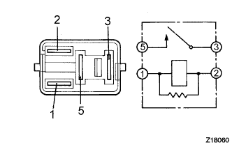 |
Remove the cooler relay assembly (MG CLT relay) from the engine room J/B.
Measure the resistance according to the value(s) in the table below.
| Tester Connection | Condition | Specified Condition |
| 3 - 5 | Always | 10 kΩ or higher |
| 3 - 5 | Battery voltage is applied between terminals 1 and 2 | Below 1 Ω |
|
| ||||
| OK | |
|
| 6.INSPECT MAGNETIC CLUTCH ASSEMBLY |
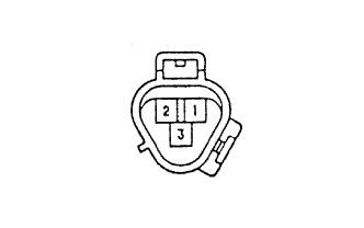 |
Disconnect the connector from the cooler compressor assembly.
Connect the battery positive (+) lead to terminal 3, check that the following occurs: 1) the magnetic clutch's operating sound can be heard, and 2) the magnetic clutch's hub and rotor lock.
|
| ||||
| OK | |
|
| 7.CHECK HARNESS AND CONNECTOR (A/C AMPLIFIER (MGC TERMINAL) - BODY GROUND) |
Check for open and short circuit in the harness and the connector between the A/C amplifier and body ground (Click here).
|
| ||||
| OK | ||
| ||
| ||
| 8.CHECK HARNESS AND CONNECTOR (A/C AMPLIFIER (AC1 TERMINAL) - ECM (AC1 TERMINAL)) |
Check for open and short circuit in the harness and the connector between the A/C amplifier and the ECM (Click here).
|
| ||||
| OK | |
|
| 9.INSPECT AIR CONDITIONING AMPLIFIER (AC1) |
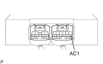 |
Remove the A/C amplifier with the connectors still connected.
Start the engine and push AUTO switch.
Measure the voltage according to the value(s) in the table below.
| Tester Connection (Symbols) | Condition | Specified Condition |
| A17-7 (AC1) - Body ground | A/C switch: OFF | 3.7 to 4.5 V |
| A17-7 (AC1) - Body ground | A/C switch: ON | 1.3 to 2.6 V |
|
| ||||
| OK | ||
| ||
| ||

