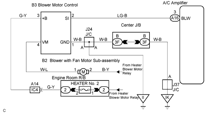
AIR CONDITIONING SYSTEM > Blower Motor Circuit |
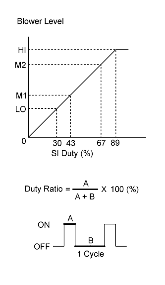
| 1.PERFORM ACTUATOR CHECK |
Operate the A/C control panel to enter the actuator check mode (Click here).
Press the blower switch and change it to the step operation.
Check the air flow temperature by hand.
| Display Code | Air Mix Damper Operation |
| 0 | 0 (No blower) |
| 1 | 1 (LO) |
| 2 | 17 (Medium) |
| 3 | 17 (Medium) |
| 4 | 17 (Medium) |
| 5 | 17 (Medium) |
| 6 | 17 (Medium) |
| 7 | 17 (Medium) |
| 8 | 17 (Medium) |
| 9 | 31 (HI) |
|
| ||||
| NG | |
 |
| 2.INSPECT FUSE (HTR NO. 2) |
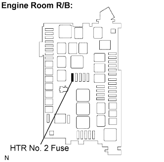 |
Remove the HTR No. 2 fuse from the engine room R/B.
Measure the resistance according to the value(s) in the table below.
| Tester Item | Condition | Specified Condition |
| HTR No. 2 fuse | Always | Below 1 Ω |
|
| ||||
| OK | |
|
| 3.INSPECT BLOWER WITH FAN MOTOR SUB-ASSEMBLY |
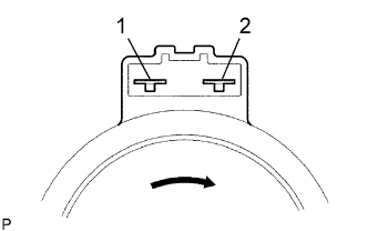 |
Remove the blower with fan motor sub-assembly.
Connect the battery positive (+) lead to terminal 2 and the battery negative (-) lead to terminal 1.
|
| ||||
| OK | |
|
| 4.CHECK HARNESS AND CONNECTOR (HEATER BLOWER MOTOR RELAY - BLOWER MOTOR CONTROL) |
Check for open and short circuit in the harness and the connector between the blower motor relay and the blower motor control (Click here).
|
| ||||
| OK | |
|
| 5.CHECK HARNESS AND CONNECTOR (BLOWER MOTOR CONTROL - BODY GROUND) |
Check for open and short circuit in the harness and the connector between the blower motor control and body ground (Click here).
|
| ||||
| OK | |
|
| 6.INSPECT AIR CONDITIONING AMPLIFIER (BLW) |
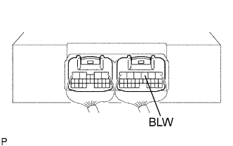 |
Remove the A/C amplifier with the connectors still connected.
Turn the ignition switch ON.
Set the blower speed to LO.
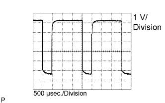 |
Measure the waveform between terminal A16-3 (BLW) of the A/C amplifier and body ground.
|
| ||||
| OK | |
|
| 7.CHECK HARNESS AND CONNECTOR (BLOWER MOTOR CONTROL - A/C AMPLIFIER) |
Check for open and short circuit in the harness and the connector between the blower motor control and the A/C amplifier (Click here).
|
| ||||
| OK | ||
 | ||
| ||
