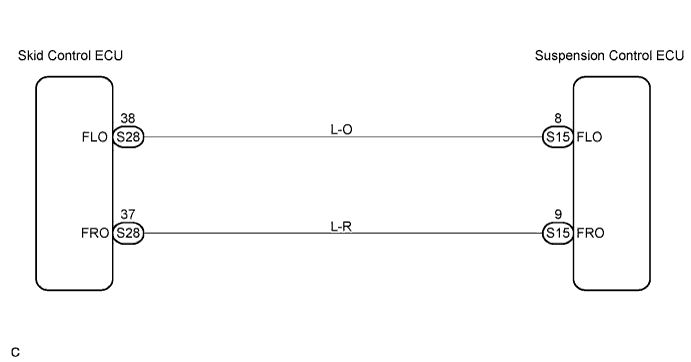
DTC C1776/76 Speed Sensor Circuit |
DTC C1794/94 Front Speed Sensor RH Circuit Malfunction |
DTC C1795/95 Front Speed Sensor LH Circuit Malfunction |
| DTC No. | DTC Detection Condition | Trouble Area |
| C1776/76 | Speed sensor circuit malfunction. |
|
| 1.READ VALUE OF INTELLIGENT TESTER |
Connect the intelligent tester to DLC3.
Turn the ignition switch ON, and push the intelligent tester main switch ON.
Select the item "VEHICLE SPEED" in the DATA LIST, and read its value displayed on the intelligent tester.
Check that there is no difference between the speed value output from the speed sensor displayed on the intelligent tester and the speed value displayed on the speedometer when driving the vehicle.
|
| ||||
| NG | |
 |
| 2.CHECK DTC (VSC SYSTEM) |
Check if the normal code is output by VSC (Click here).
|
| ||||
| OK | |
|
| 3.CHECK HARNESS AND CONNECTOR (SUSPENSION CONTROL ECU - SKID CONTROL ECU) |
Check for open and short circuit in the harness and the connector between the suspension control ECU and the skid control ECU (Click here).
|
| ||||
| OK | |
|
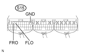
| 4.INSPECT SUSPENSION CONTROL ECU (FLO SIGNAL, FRO SIGNAL) |
 |
Remove the suspension control ECU with connector still connected.
Turn the ignition switch ON.
Connect an oscilloscope to between terminals S15-8 (FLO) and S15-1 (GND) and between terminals S15-9 (FRO) and S15-1 (GND) of the suspension control ECU harness side connector.
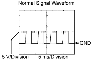 |
Drive the vehicle with about 20 km/h (12 mph), and check the signal waveform.
|
| ||||
| OK | ||
 | ||
| ||
