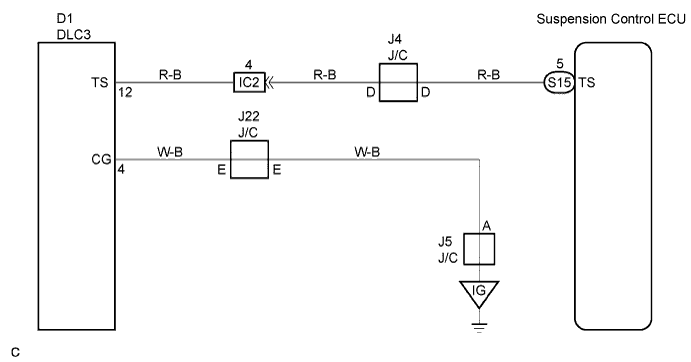
AIR SUSPENSION SYSTEM > TS and CG Terminal Circuit |
| 1.CHECK DLC3 TERMINAL VOLTAGE (TS TERMINAL) |
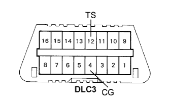 |
Turn the ignition switch to the ON position.
Measure voltage between terminals TS and CG of DLC3.
|
| ||||
| NG | |
 |
| 2.CHECK HARNESS AND CONNECTOR (DLC3 - BODY GROUND) |
Check for open and short circuit in the harness and the connector between terminal CG of DLC3 and body ground (Click here).
|
| ||||
| OK | |
|
| 3.CHECK HARNESS AND CONNECTOR (DLC3 - SUSPENSION CONTROL ECU) |
Check for open and short circuit in the harness and the connector between terminal TS of DLC3 and the suspension control ECU (Click here).
|
| ||||
| OK | ||
 | ||
| ||

