 |
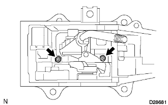
Install the shift lock control computer with the 2 screws.
SHIFT LEVER ASSEMBLY > REASSEMBLY |
| 1. INSTALL SHIFT LOCK CONTROL COMPUTER SUB-ASSEMBLY |
|
Install the shift lock control computer with the 2 screws.
Install the spring and shift lock release link.
Install the shift lever guide housing.
Install the lever lock and shift lever nut.
| 2. INSTALL INDICATOR LAMP WIRE SUB-ASSEMBLY |
Install the bulb to the indicator lamp wire sub-assembly.
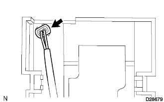 |
Install the indicator lamp wire sub-assembly.
| 3. INSTALL SHIFT LOCK RELEASE BUTTON COVER |
| 4. INSTALL SHIFT LOCK RELEASE BUTTON |
| 5. INSTALL LOWER POSITION INDICATOR HOUSING |
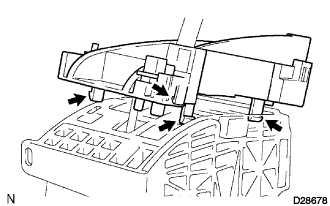 |
Install the lower position indicator housing.
Connect the 3 clamps of indicator lamp wire sub-assembly.
| 6. INSTALL FLOOR SHIFT POSITION INDICATOR HOUSING SUB-ASSEMBLY |
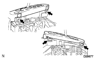 |
Install the slide cover and floor shift position indicator housing sub-assembly to the shift lever guide housing.
| 7. INSTALL SHIFT LEVER KNOB SUB-ASSEMBLY |
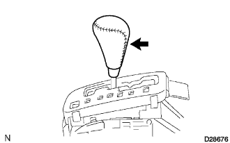 |
Install the floor shift lever knob to the shift lever.