CYLINDER HEAD > INSTALLATION |
| 1. INSTALL NO. 2 CYLINDER HEAD GASKET |
![]() |
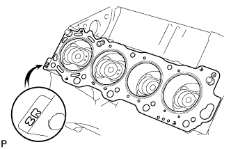
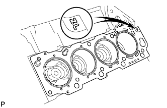
Place a new cylinder head gasket in position on the cylinder block.
Place the cylinder head in position on the cylinder head gasket.
| 2. INSTALL CYLINDER HEAD GASKET |
![]() |
Place a new cylinder head gasket in position on the cylinder block.
Place the cylinder head in position on the cylinder head gasket.
| 3. INSTALL CYLINDER HEAD SUB-ASSEMBLY LH |
![]() |
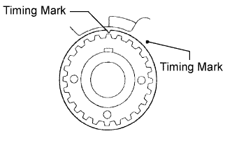
Check that the timing mark of the crankshaft timing pulley is in the position shown in the illustration, and that the piston is below the TDC of compression.
Install the cylinder head with the exhaust manifold to the cylinder block.
Apply a light coat of engine oil to the threads and under the heads of the cylinder head bolts.
Install the plate washer to the cylinder head bolt.
![]() |
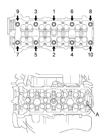
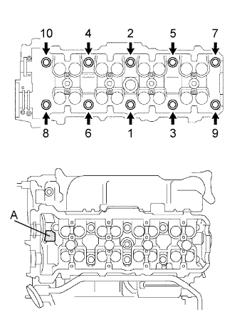
Install and uniformly tighten the 10 cylinder head bolts, and plate washers, in the order shown in the illustration.
![]() |
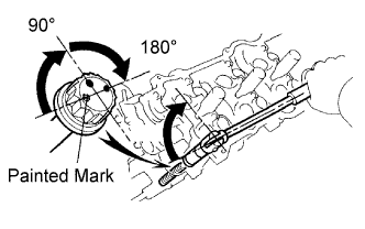
Mark the front of the cylinder head bolt head with paint.
Retighten the cylinder head bolts by 90° in the order shown.
Retighten the cylinder head bolts by an additional 90°.
Check that the painted mark is now at a 180° angle to front.
| 4. INSTALL CYLINDER HEAD SUB-ASSEMBLY |
![]() |
Check that the timing mark of the crankshaft timing pulley is in the position shown in the illustration, and that the piston is below the TDC of compression.
Install the cylinder head with the exhaust manifold to the cylinder block.
Apply a light coat of engine oil to the threads and under the heads of the cylinder head bolts.
Install the plate washer to the cylinder head bolt.
![]() |
Install and uniformly tighten the 10 cylinder head bolts, and plate washers, in the order shown in the illustration.
![]() |
Mark the front of the cylinder head bolt head with paint.
Retighten the cylinder head bolts by 90° in the order shown.
Retighten the cylinder head bolts by an additional 90°.
Check that the painted mark is now at a 180° angle to front.
| 5. INSTALL FRONT EXHAUST PIPE |
Place a new gasket to the front exhaust pipe.
Install the 2 nuts and front exhaust pipe.
| 6. INSTALL REAR TIMING BELT PLATE LH |
Install the bolt and rear timing belt plate LH.
| 7. INSTALL NO. 2 REAR TIMING BELT PLATE LH |
Install the 2 bolts and No. 2 rear timing belt plate LH.
| 8. INSTALL REAR TIMING BELT PLATE RH |
Install the timing belt plate with the bolt and stud bolt.
| 9. INSTALL NO. 2 REAR TIMING BELT PLATE RH |
Install the timing belt plate with the 2 bolts.
| 10. INSTALL WATER BY-PASS JOINT RR |
![]() |
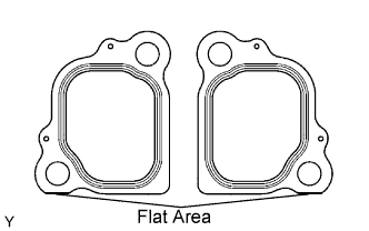
With the flat-bottom of each new gasket facing downward as shown in the illustration, install the 2 gaskets to the engine rear side.
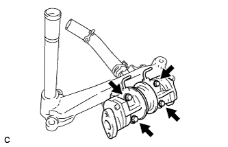
Install the water by-pass joint with the 4 nuts. Alternately tighten the nuts.
| 11. INSTALL NO. 2 AIR SWITCHING VALVE |
![]() |
Install 2 new gaskets and the 2 No. 2 air switching valves with the 4 bolts to the water by-pass joint rear.
Connect the 2 vacuum hoses to the No. 2 air switching valves.
| 12. INSTALL WATER BY-PASS JOINT FR |
![]() |
With the flat-bottom of each new gasket facing downward as shown in the illustration, install the 2 gaskets to the engine front side.
Install the water by-pass joint with the 4 nuts. Alternately tighten the nuts.
| 13. INSTALL WATER INLET HOUSING |
Install the water inlet with the 3 nuts.
| 14. INSTALL WATER BY-PASS PIPE SUB-ASSEMBLY |
Install a new O-ring to the water by-pass pipe.
Apply soapy water to the O-ring.
Push in the water by-pass pipe end into the pipe hole of the water pump.
Install the water by-pass pipe with the bolt.
| 15. INSTALL INTAKE MANIFOLD ASSEMBLY |
![]() |
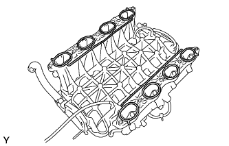
Place 2 new gaskets on the intake manifold.
![]() |
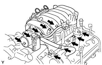
Place the intake manifold on the cylinder heads.
Install and uniformly tighten the 6 bolts and 4 nuts in several steps.
![]() |
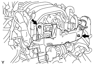
Install the V-bank cover bracket to the intake manifold.
Install the wire bracket to the intake manifold with the bolt.
Connect the engine wire to the engine hanger and wire bracket.
![]() |
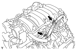
Connect the wire protector to the intake manifold and cylinder heads with the bolt and nut.
Install the 2 ground cables with the 2 bolts to the RH and LH cylinder heads.
![]() |
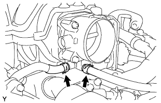
Connect the 2 water by-pass hoses to the throttle body.
![]() |
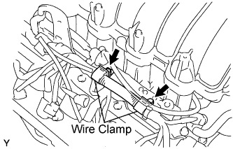
Connect the 2 wire clamps to the wire clamp bracket on the RH delivery pipe.
| 16. INSTALL OIL LEVEL GAGE GUIDE |
Install a new O-ring to the oil level gauge guide.
Install the oil level gauge guide with the bolt.
| 17. INSTALL TRANSMISSION OIL FILLER TUBE SUB-ASSEMBLY |
Install the transmission oil filler tube sub-assembly with the bolt.
| 18. INSTALL CAMSHAFT (for LH Side) |
![]() |
Apply MP grease to the thrust portions of the camshafts.
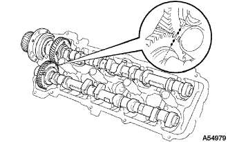
Align the timing marks (2-dot marks) of the camshaft drive and driven main gears, and place the 2 camshafts.
![]() |
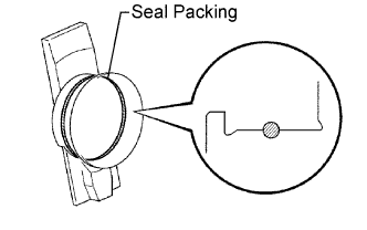
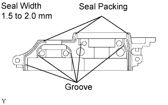
Apply seal packing to the camshaft housing plug.
![]() |
Install the camshaft housing plug and oil control valve filter to the cylinder head as shown in the illustration.
![]() |
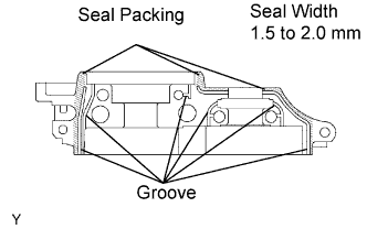
Apply seal packing to the front bearing cap.
![]() |
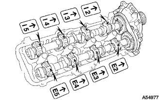
Install the front bearing cap.
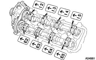
Install the other bearing cap in the order shown with the arrow mark facing forward.
![]() |
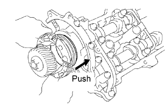
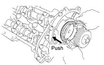
Push in the camshaft setting oil seal.
![]() |
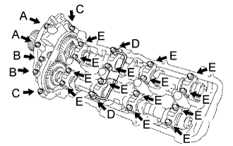
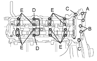
Install a new seal washer to the bearing cap bolt (A and B).
Apply a light coat of engine oil to the threads and under the heads of the bearing cap bolts (D and E).
Install the camshafts of the LH bank.
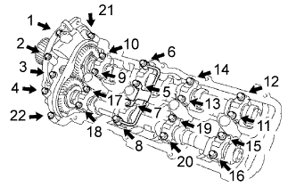
Install the oil feed pipe and the 22 bearing cap bolts as shown in the illustration.
![]() |
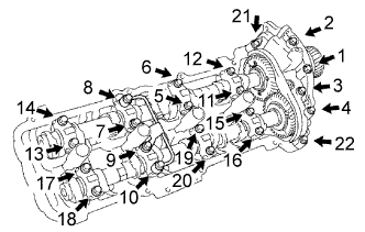
Uniformly tighten the 22 bearing cap bolts in several steps, in the order shown in the illustration.
![]() |
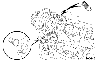
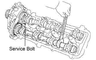
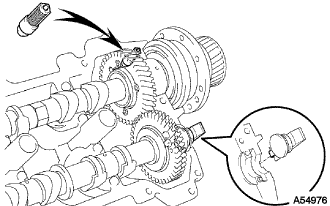
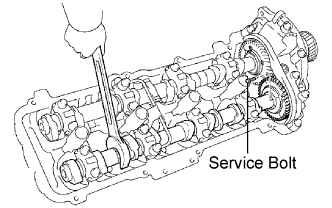
Bring the service bolt installed in the driven sub-gear upward by turning the hexagonal portion of the camshaft with a wrench.
Remove the service bolt.
| 19. INSTALL CAMSHAFT (for RH Side) |
![]() |
![]() |
Apply engine oil to the thrust portion of the intake and exhaust camshafts.
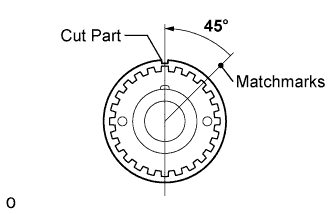
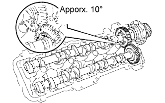
Align the timing marks (1-dot mark) of the camshaft drive and driven main gears, and place the 2 camshafts.
Set the timing marks (1-dot mark) of the camshaft drive and driven main gears at approx. 10° angle.
![]() |
Apply seal packing to the camshaft housing plug.
![]() |
Install the camshaft housing plug and oil control valve filter to the cylinder head as shown in the illustration.
![]() |
Apply seal packing to the front bearing cap.
![]() |
Install the front bearing cap.
Install the other bearing caps in the order shown with the arrow mark facing forward.
![]() |
Push in the camshaft setting oil seal.
![]() |
Install new seal washers to the bearing cap bolts (A and B).
Apply a light coat of engine oil to the threads and under the heads of the bearing cap bolts (D and E).
Install the oil feed pipe and the 22 bearing cap bolts as shown in the illustration.
![]() |
Uniformly tighten the 22 bearing cap bolts in several steps, in the order shown in the illustration.
![]() |
Bring the service bolt installed in the driven sub-gear upward by turning the hexagonal portion of the camshaft with a wrench.
Remove the service bolt.
| 20. INSTALL TIMING BELT |