 |
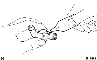
Apply adhesive to 2 or 3 threads.
- Adhesive:
- Part No. 08833-00070, THREE BOND 1324 or equivalent
ENGINE ASSEMBLY > INSTALLATION |
| 1. INSTALL VENTILATION VALVE SUB-ASSEMBLY |
|
Apply adhesive to 2 or 3 threads.
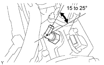 |
Install the ventilation valve.
Install the ventilation valve cover to the ventilation valve.
Connect the ventilation hose to the ventilation valve.
| 2. INSTALL OIL COOLER ASSEMBLY |
Place a new gasket into the groove of the oil cooler.
Apply a light coat of engine oil to the gasket.
Install the oil cooler assembly with the 2 bolts and nut.
| 3. INSTALL EXHAUST MANIFOLD SUB-ASSEMBLY LH |
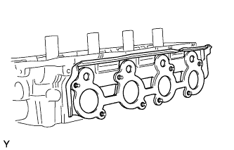 |
Place a new gasket on the cylinder head.
Install the exhaust manifold with 8 new nuts. Uniformly tighten the nuts in diagonally.
Install the heat insulator with the 4 bolts.
| 4. INSTALL EXHAUST MANIFOLD SUB-ASSEMBLY RH |
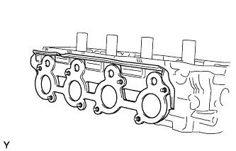 |
Place a new gasket on the cylinder head.
Install the exhaust manifold with 8 new nuts. Uniformly tighten the nuts diagonally.
Install the heat insulator with the 4 bolts.
| 5. INSTALL WATER BY-PASS JOINT FR |
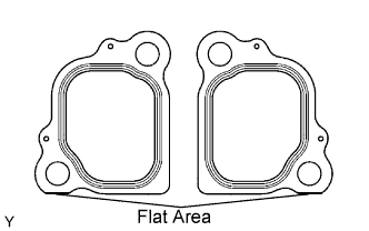 |
With the flat-bottom of each new gasket facing downward as shown in the illustration, install the 2 gaskets to the engine front side.
Install the water by-pass joint with the 4 nuts. Alternately tighten the nuts.
| 6. INSTALL WATER INLET HOUSING |
Install the water inlet with the 3 nuts.
| 7. INSTALL KNOCK SENSOR |
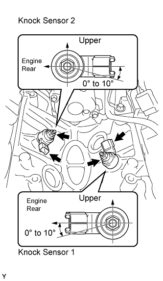 |
Install the 2 knock sensors with the 2 nuts as shown in the illustration.
Connect the 2 knock sensor connectors.
| 8. INSTALL STARTER ASSEMBLY |
Install the starter assembly with the 2 bolts.
Connect the No. 2 engine wire.
| 9. INSTALL AIR PUMP ASSEMBLY WITH BRACKET |
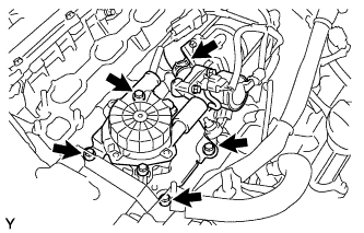 |
Install the air pump assembly with the 4 bolts.
Connect the pressure sensor connector for the air injection system.
Connect the air switching valve connector.
Connect the No. 2 air hose to the air switching valve.
| 10. INSTALL WATER BY-PASS JOINT RR |
|
With the flat-bottom of each new gasket facing downward as shown in the illustration, install the 2 gaskets to the engine rear side.
Install the water by-pass joint with the 4 nuts. Alternately tighten the nuts.
| 11. INSTALL NO. 2 AIR SWITCHING VALVE |
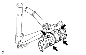 |
Install 2 new gaskets and the 2 No. 2 air switching valves with the 4 bolts to the water by-pass joint rear.
Connect the 2 vacuum hoses to the No. 2 air switching valves.
| 12. INSTALL WATER BY-PASS PIPE SUB-ASSEMBLY |
Install a new O-ring to the water by-pass pipe.
Apply soapy water to the O-ring.
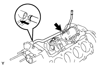 |
Push in the water by-pass pipe end into the pipe hole of the water pump.
Install the water by-pass pipe with the bolt.
| 13. INSTALL VVT SENSOR |
Install the VVT sensors with the 2 bolts.
| 14. INSTALL CRANKSHAFT POSITION SENSOR |
Install the crankshaft position sensor with the bolt.
| 15. INSTALL CAMSHAFT POSITION SENSOR |
Install the camshaft position sensor with the bolt and the stud bolt.
| 16. INSTALL IGNITION COIL ASSEMBLY |
Install the 8 ignition coils with the 8 bolts.
| 17. INSTALL FAN BRACKET SUB-ASSEMBLY |
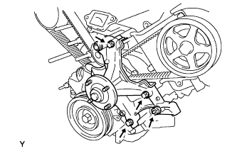 |
Install the fan bracket with the 2 bolts and 2 nuts.
| 18. INSTALL V-RIBBED BELT TENSIONER ASSEMBLY |
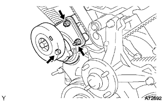 |
Install the v-ribbed belt tensioner with the bolt and 2 nuts.
| 19. INSTALL NO. 2 TIMING BELT COVER SUB-ASSEMBLY |
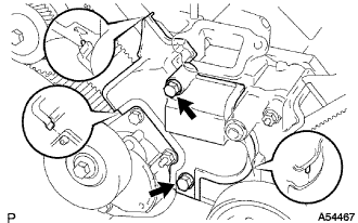 |
Install the No. 2 timing belt cover sub-assembly with the 2 bolts.
| 20. INSTALL NO. 2 TIMING CHAIN OR BELT COVER |
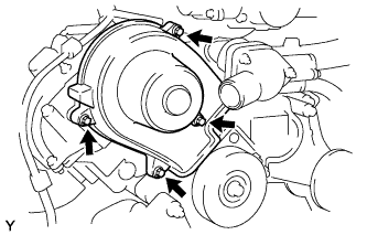 |
Install the timing chain or belt cover with the nut and 3 bolts.
| 21. INSTALL NO. 3 TIMING BELT COVER SUB-ASSEMBLY LH |
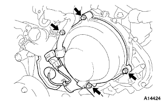 |
Install the timing belt cover sub-assembly with the 4 bolts.
Install the camshaft position sensor connector and grommet to the timing belt cover.
| 22. INSTALL PUMP BRACKET |
Install the pump bracket with the 4 bolts.
| 23. INSTALL OIL COOLER PIPE |
Install the oil cooler pipe with the bolt and nut.
Connect the 3 hoses.
| 24. INSTALL DRIVE PLATE & RING GEAR SUB-ASSEMBLY |
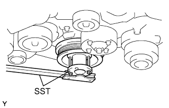 |
Using SST, hold the crankshaft.
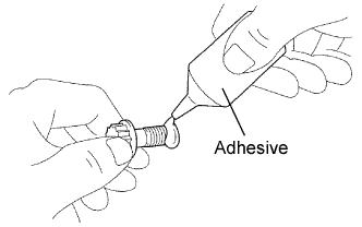 |
Apply adhesive to 2 or 3 threads of the mounting bolt end.
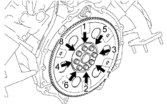 |
Install the front spacer, drive plate and rear spacer on the crankshaft.
Install and uniformly tighten the 8 mounting bolts in several steps, in the order shown in the illustration.
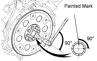 |
Mark the mounting bolt with paint (Procedure "A").
Retighten the mounting bolts by 90° in the order shown.
Check that the painted mark is now at a 90° angle to the mark placed in procedure "A".
| 25. INSTALL HEATER HOSE |
| 26. INSTALL GENERATOR ASSEMBLY |
Install the generator with the bolt and 2 nuts.
Connect the generator connector.
Connect the generator wire with the nut and rubber cap.
Install the generator wire clamp to the cord clip on the generator.
| 27. INSTALL NO. 1 ENGINE MOUNTING BRACKET FRONT LH |
Install the engine-mounting bracket and engine-mounting insulator with the 4 bolts.
| 28. INSTALL NO. 1 ENGINE MOUNTING BRACKET FRONT RH |
Install the engine-mounting bracket and engine-mounting insulator with the 4 bolts.
| 29. INSTALL NO. 2 ENGINE WIRE |
Install the engine wire protector with the nut and 2 bolts.
Connect the ground cable wire clamp with the bolt.
| 30. INSTALL NO. 2 WIRING HARNESS HEAT INSULATOR |
Install the wiring harness heat insulator with the 2 bolts.
| 31. INSTALL INTAKE MANIFOLD ASSEMBLY |
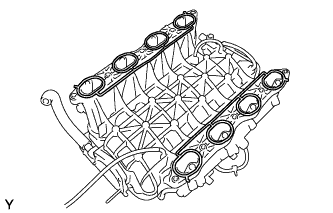 |
Place 2 new gaskets on the intake manifold.
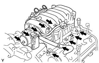 |
Place the intake manifold on the cylinder heads.
Install and uniformly tighten the 6 bolts and 4 nuts in several steps.
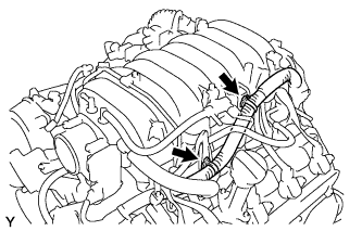 |
Install the V-bank cover bracket to the intake manifold.
Install the wire bracket to the intake manifold with the bolt.
Connect the engine wire to the engine hanger and wire bracket.
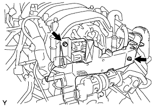 |
Connect the wire protector to the intake manifold and cylinder heads with the bolt and nut.
Install the 2 ground cables with the 2 bolts to the RH and LH cylinder heads.
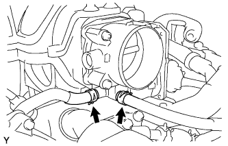 |
Connect the 2 water by-pass hoses to the throttle body.
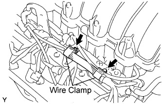 |
Connect the 2 wire clamps to the wire clamp bracket on the RH delivery pipe.
| 32. INSTALL ENGINE WIRE |
| 33. INSTALL ENGINE ASSEMBLY |
Attach the engine chain hoist to the engine hangers.
Slowly lower the engine assembly into the engine compartment.
Attach the engine mounting brackets to the frame brackets.
Install the engine mounting brackets with the 4 nuts and 4 bolts.
Remove the engine chain hoist.
| 34. INSTALL ENGINE WIRE |
| 35. CONNECT HEATER HOSE |
| 36. INSTALL OIL LEVEL GAUGE GUIDE |
Install a new O-ring to the oil level gauge guide.
Install the oil level gauge guide with the bolt.
| 37. INSTALL TRANSMISSION OIL FILLER TUBE SUB-ASSEMBLY |
Install a new O-ring to the oil filler tube sub-assembly.
Install the transmission oil filler tube sub-assembly with the bolt.
| 38. INSTALL FAN WITH FLUID COUPLING |
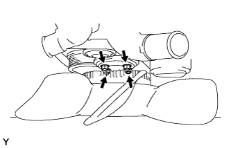 |
Install the fan pulley to the engine.
Install the fan with fluid coupling with the 4 nuts.
| 39. INSTALL COMPRESSOR |
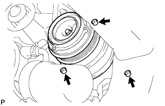 |
Install the compressor with the stay, nut and 3 bolts.
Connect the compressor connector.
| 40. INSTALL VANE PUMP ASSEMBLY |
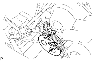 |
Install the vane pump assembly with the nut and 2 bolts.
| 41. INSTALL FAN AND GENERATOR V BELT |
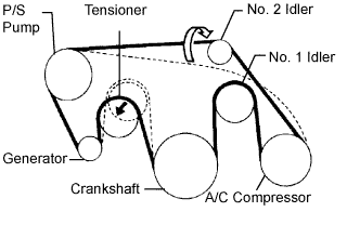 |
Set the V belt onto every parts except the No. 2 idler pulley, as shown in the illustration.
Loosen the V belt by turning the belt tensioner counterclockwise.
Set the V belt to the No. 2 idler pulley.
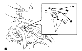 |
After installing a new belt, check that the mark is within the B range as shown in the illustration.
| 42. CONNECT FUEL VAPOR FEED HOSE ASSEMBLY |
| 43. CONNECT FUEL HOSE |
| 44. CONNECT NO. 2 FUEL HOSE |
| 45. INSTALL FAN SHROUD |
Install the fan shroud with the fan into the engine room.
| 46. INSTALL RADIATOR ASSEMBLY |
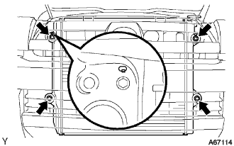 |
Insert the tabs of the radiator support through the radiator service holes.
Install the radiator assembly with the 4 bolts.
| 47. ADD ENGINE COOLANT |
Slowly fill the system with engine coolant.
Install the radiator cap securely.
Bleed the cooling system.
Open the heater water valve while warming up the engine.
Maintain the engine speed at 2,000 to 2,500 rpm and warm up the engine.
Stop the engine and wait until the coolant cools down.
Add coolant into the reservoir until the coolant level is FULL.
| 48. ADD ENGINE OIL |
| 49. INSTALL ENGINE UNDER COVER ASSEMBLY REAR |
| 50. INSTALL NO. 1 ENGINE UNDER COVER SUB-ASSEMBLY |
| 51. INSTALL AIR CLEANER ASSEMBLY |
Install the air cleaner assembly with the 3 bolts.
Connect the wire harness clamp and the ground cable.
| 52. INSTALL AIR CLEANER HOSE ASSEMBLY |
| 53. INSTALL THROTTLE BODY COVER SUB-ASSEMBLY |
Install the throttle body cover sub-assembly with the 2 nuts.
| 54. INSTALL HOOD SUB-ASSEMBLY |
Install the hood with the 4 bolts.
Connect the hood damper.
Connect the windshield washer hose.
| 55. INSTALL AUTOMATIC TRANSMISSION ASSEMBLY (for 2WD) |
| 56. INSTALL AUTOMATIC TRANSMISSION ASSEMBLY (for 4WD) |
| 57. CHECK FOR ENGINE COOLANT LEAKAGE |
Fill the radiator with coolant and attach a radiator cap tester.
Pump it to 118 kPa (1.2 kgf/cm2 17.1 psi), then check for leakage.
| 58. CHECK FOR EXHAUST GAS LEAKAGE |
| 59. CHECK FOR FUEL LEAKAGE |
When using the intelligent tester
Connect the intelligent tester to the DLC3.
Turn the ignition switch ON and intelligent tester main switch ON.
Select the ACTIVE TEST mode on the intelligent tester.
Please refer to the intelligent tester operator's manual for further details.
 |
When not using the intelligent tester
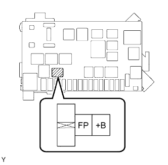
Remove the circuit opening relay.
Using a service wire, connect terminals FP and +B of the relay block.
Turn the ignition switch ON, and check that the fuel pump operates.
Check that there are no fuel leaks after doing maintenance anywhere on the fuel system.
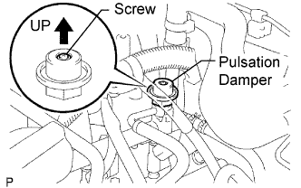 |
Check that the pulsation damper screw rises up when the fuel pump operates.
If operation is not as specified, check the following parts:
Turn the ignition switch OFF.
Disconnect the intelligent tester from the DLC3.
| 60. INSPECT AUTOMATIC TRANSMISSION FLUID |
| 61. CHECK FOR ENGINE OIL LEAKAGE |