Home › ENGINE ยท 2UZ-FE › ENGINE MECHANICAL › ENGINE UNIT

ENGINE UNIT > REASSEMBLY

for Preparation Click here


HINT:
  1. Thoroughly clean all parts to be assembled.
  2. Before installing the parts, apply new engine oil to all sliding and rotating surfaces.
  3. Replace all gaskets, O-rings and oil seals with new ones.


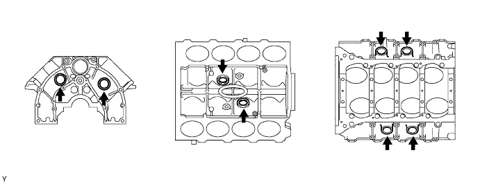
1. INSTALL TIGHT PLUG


  1. Install the tight plug.


    A072720E01


      A072721E01
    1. Apply adhesive to the tight plug.

      Adhesive:
      Part No. 08833-00070, THRE BOND 1324 or equivalent

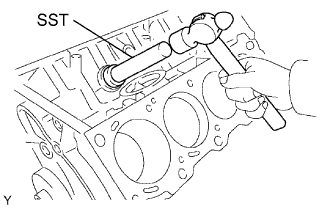
    2. Using SST and a hammer, tap in a new tight plug as shown in the illustration.

      SST
      09950-60010   (09951-00350)
      09950-70010   (09951-07100)


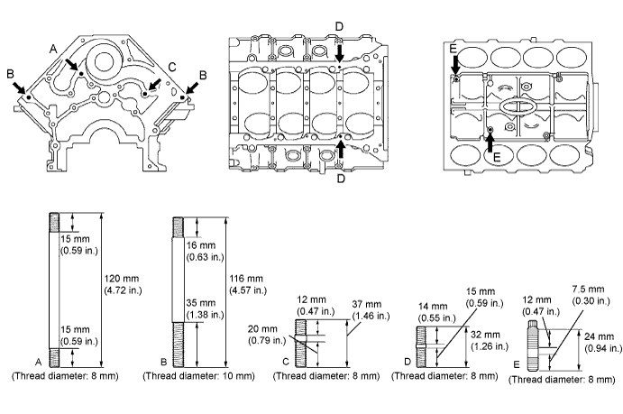
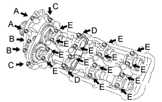
2. INSTALL STUD BOLT


  1. Install the stud bolt.


    G039840E01

    Torque:
    For A:
    8.0 N*m{ 80 kgf*cm , 71 in.*lbf }
    For B:
    20 N*m{ 200 kgf*cm , 14 ft.*lbf }
    For C:
    12 N*m{ 120 kgf*cm , 9 ft.*lbf }
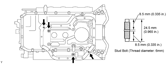
    For D:
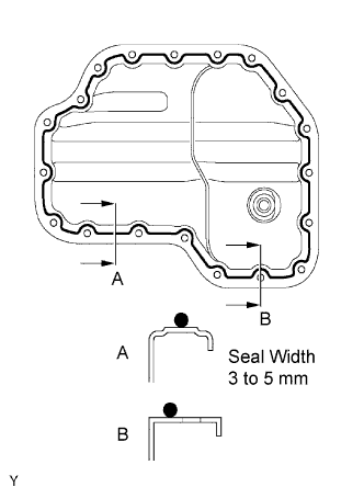
    14 N*m{ 145 kgf*cm , 10 ft.*lbf }
    For E:
    8.0 N*m{ 80 kgf*cm , 71 ft.*lbf }


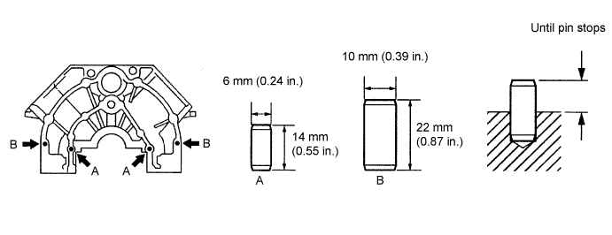
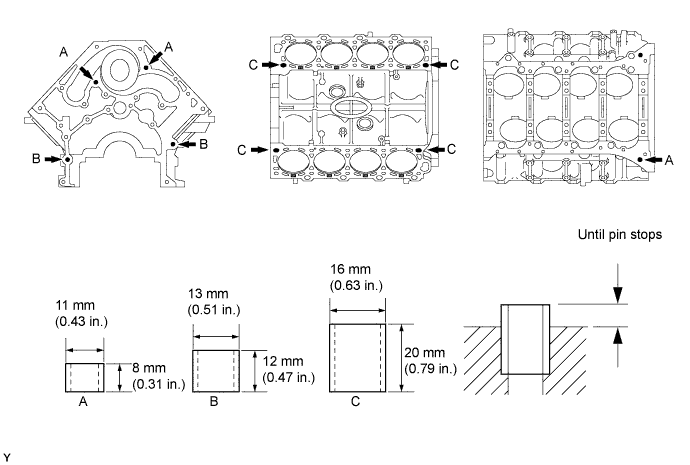
3. INSTALL STRAIGHT PIN


  1. Install the straight pin.


    A053947E02


4. INSTALL RING PIN


  1. Install the ring pin.


    A134388E01


5. INSTALL PISTON


    A004861
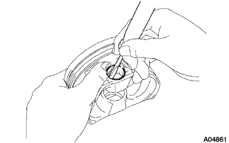
  1. Using a screwdriver, install a new snap ring on one side of the piston pin hole.


    A004876E02
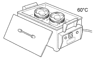
  1. Gradually heat the piston to about 60°C (140°F).


    A134389E01
  1. Coat the piston pin with engine oil.

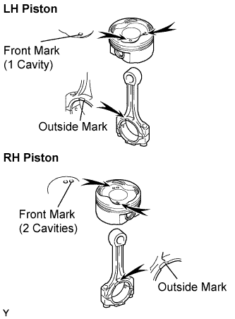
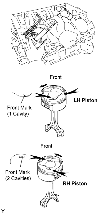
  1. Position the piston front mark with respect to the outside mark on the connecting rod as shown in the illustration.

    NOTICE:
    The installation directions of the piston and connecting rod are different for the LH and RH banks. The LH piston is marked with 1 cavity and "2", the RH piston with 2 cavities and "2".

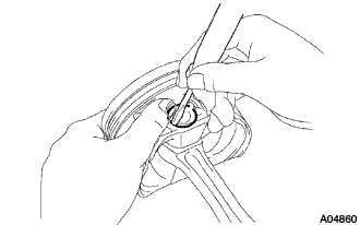
  1. Align the piston pin holes of the piston and connecting rod, and push in the piston pin with your thumb.


    A004860
  1. Using a screwdriver, install a new snap ring on the other side of the piston pin hole.


6. INSTALL PISTON RING SET
  1. Install the oil ring expander and 2 side rails by hand.


    A134390E01
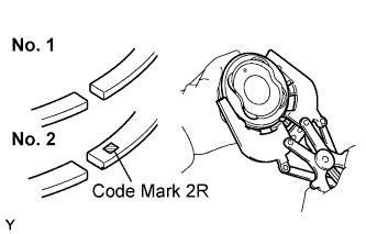
  1. Using a piston ring expander, install the 2 piston rings with the code mark facing upward.
    Code mark: 
    No. 1
    None
    No. 2
    2R


    A054735E01
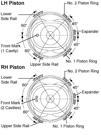
  1. Position the piston rings so that the ring ends are as shown in the illustration.

    NOTICE:
    Do not align the ring ends.


7. INSTALL CONNECTING ROD BEARING


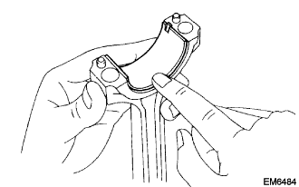
    EM06484
  1. Align the bearing claw with the groove of the connecting rod or connecting cap.

  1. Install the bearings in the connecting rod and connecting rod cap.


8. INSTALL CRANKSHAFT BEARING

HINT:
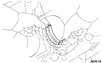
  1. Main bearings come in widths of 19.5 mm (0.768 in.) and 22.5 mm (0.886 in.). Install the 22.5 mm (0.886 in.) bearings in the No. 1 and No. 5 cylinder block journal positions with the crankshaft bearing cap. Install the 19.5 mm (0.768 in.) bearings in the other positions.
  2. Upper bearings have an oil groove and oil holes; lower bearings do not.


    A004216
  1. Align the bearing claw with the claw groove of the cylinder block, and push in the 5 upper bearings.


    A004214E02
  1. Align the bearing claw with the claw groove of the crankshaft bearing cap, and push in the 5 lower bearings.

    HINT:
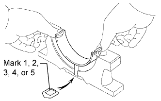
    A number is marked on each bearing cap to indicate the installation position.


9. INSTALL CRANKSHAFT THRUST WASHER SET


    A066654
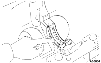
  1. Install the 2 thrust washers under the No. 3 journal position of the cylinder block with the oil grooves facing outward.


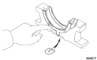
    A004217
  1. Install the 2 thrust washers on the No. 3 bearing cap with the grooves facing outward.


10. INSTALL CRANKSHAFT PULLEY SET CRANKSHAFT KEY


11. INSTALL CRANKSHAFT


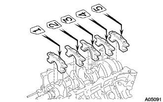
    A005091
  1. Place the crankshaft on the cylinder block.

  1. Install the 5 crankshaft bearing caps in their proper locations.

    HINT:
    Place the bearing caps level and let them return to their original positions by their own weight.

    NOTICE:
    Do not install the bearing cap by tapping it.


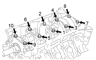
    A005095E02
  1. Install the crankshaft bearing cap bolts.

    HINT:
    1. The bearing cap bolts are tightened in 2 progressive steps.
    2. If any one of the bearing cap bolts is broken or deformed, replace it.


    1. Apply a light coat of engine oil to the threads and under the heads of the crankshaft bearing cap bolts.

    2. Install and uniformly tighten the 10 crankshaft bearing cap bolts in several steps, in the order shown in the illustration.

      Torque:
      27 N*m{ 275 kgf*cm , 20 in.*lbf }

      If any one of the bearing cap bolts does not meet the torque specification, replace the bearing cap bolt.


    3. A005094E02
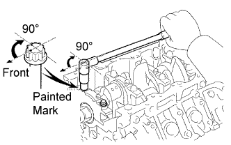
    4. Mark the front of the crankshaft bearing cap bolts with paint.

    5. Retighten the crankshaft bearing cap bolts by 90° in the order shown.

    6. Check that the painted mark is now at a 90° angle to the front.

    7. Check that the crankshaft turns smoothly.


12. INSTALL PISTON AND CONNECTING ROD


    A134391E01
  1. Using a piston ring compressor, push the correctly numbered piston and connecting rod assemblies into each cylinder with the front mark of the piston facing forward.

    NOTICE:
    The shape of the piston varies for the LH and RH banks. The LH piston is marked with 1 cavity and "2", the RH piston with 2 cavities and "2".


    A005106
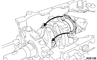
  1. Place the connecting rod cap on the connecting rod.

    1. Match the numbered connecting rod cap with the connecting rod.

    2. Align the pin groove of the connecting rod cap with the pins of the connecting rod, and install the connecting rod cap.


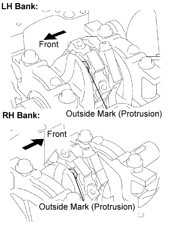
    3. A005174E02
    4. Check that the outside mark of the connecting rod cap is facing in the correct direction.


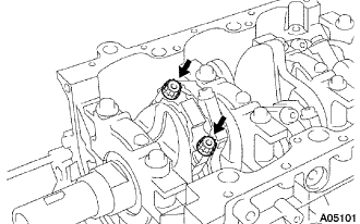
    A005101
  1. Install the connecting rod cap bolts.

    HINT:
    1. The connecting rod cap bolts are tightened in 2 progressive steps.
    2. If any one of the connecting rod cap bolts is broken or deformed, replace it.


    1. Apply a light coat of engine oil to the threads and under the heads of the connecting rod cap bolts.

    2. Install and alternately tighten the 2 connecting rod cap bolts in several steps.

      Torque:
      25 N*m{ 250 kgf*cm , 18 ft.*lbf }

      If any one of the connecting rod cap bolts does not meet the torque specification, replace the connecting rod cap bolts.


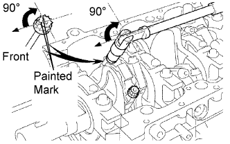
    3. A005099E02
    4. Mark the front of the connecting cap bolt with paint.

    5. Retighten the cap bolts 90° as shown in the illustration.

    6. Check that the painted mark is now at a 90° angle to the front.

  1. Check that the crankshaft turns smoothly.


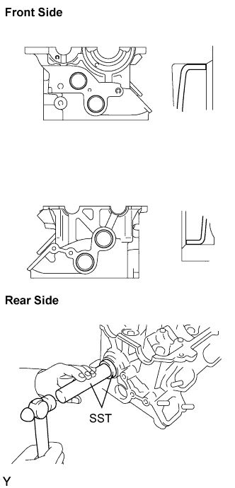
13. INSTALL NO. 1 TIGHT PLUG


    A134385E01
  1. Apply adhesive to the tight plug.

    Adhesive:
    Part No. 08833-00070, THRE BOND 1324 or equivalent

  1. Using SST and a hammer, tap in a new tight plug as shown in the illustration.

    SST
    09950-60010   (09951-00300)
    09950-70010   (09951-07100)


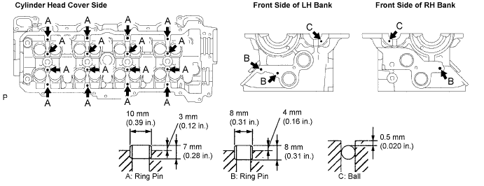
14. INSTALL CAMSHAFT BEARING CAP SETTING RING PIN


  1. Install the camshaft bearing cap setting ring pin.


    A053859E01


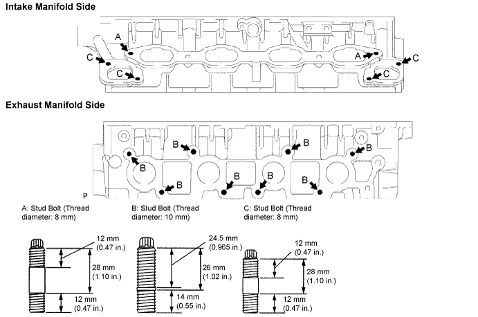
15. INSTALL STUD BOLT


  1. Install the stud bolt.


    A053860E01

    Torque:
    For A and C:
    9.0 N*m{ 90 kgf*cm , 80 in.*lbf }
    For B:
    15. N*m{ 150 kgf*cm , 11 ft.*lbf }


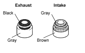
16. INSTALL VALVE STEM OIL SEAL


    A053861E03
  1. Apply a light coat of engine oil to a new oil seal.

    NOTICE:
    Pay close attention when installing the intake and exhaust oil seals. For example, installing the intake oil seal into the exhaust or installing the exhaust oil seal to the intake can cause installation problems later.

    HINT:
    The intake valve oil seal is gray/brown and the exhaust valve oil seal is black/gray.


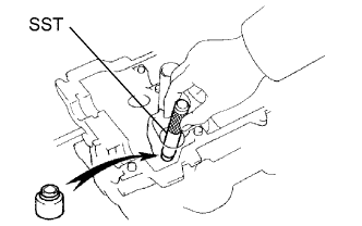
    A053857E02
  1. Using SST, push in a new oil seal.

    SST
    09201-41020  

    NOTICE:
    Failure to use SST will cause the seal to be damaged or improperly seated.


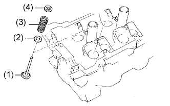
17. INSTALL VALVE


    A005711E01
  1. Install the following parts:

    1. Valve (1)

    2. Spring seat (2)

    3. Valve spring (3)

    4. Spring retainer (4)


    A005712E01
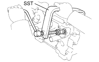
  1. Using SST, compress the valve spring and place the 2 spring retainer locks around the valve stem.

    SST
    09202-70020   (09202-00010)


    A054352E02
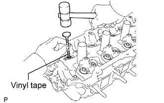
  1. Using a plastic hammer and the valve stem (not in use) tip wrapped with vinyl tape, lightly tap the valve stem tip to assure proper fit.

    NOTICE:
    Be careful not do damage the valve stem tip.


18. INSTALL VALVE LIFTER
  1. Install the valve lifter and shim.

  1. Check that the valve lifter rotates smoothly by hand.


19. INSTALL SPARK PLUG TUBE GASKET


    A004108E01
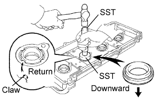
  1. Using SST and a hammer, tap in a new gasket until its surface is flush with the upper edge of the cylinder head cover.

    SST
    09950-60010   (09951-00240, 09951-00440, 09952-06010)
    09950-70010   (09951-07100)

    NOTICE:
    Be careful of the installation direction.
  1. Apply a light coat of MP grease to the gasket lip.

  1. Return the 4 ventilation case claws to the original positions.


20. INSTALL CAMSHAFT SETTING OIL SEAL


    A054966E01
  1. Insert a new oil seal into the camshaft timing tube until it reaches the stopper.

    NOTICE:
    1. Be careful of the installation direction.
    2. Do not turn over the oil seal lip.


21. INSTALL CAMSHAFT TIMING TUBE ASSEMBLY


    A054965E03
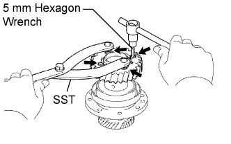
  1. Align the timing tube knock pin with the knock pin groove of the drive gear, and temporarily install the drive gear with the 4 bolts.

  1. Using SST and a 5 mm hexagon wrench, uniformly tighten the 4 bolts in several steps.

    SST
    09960-10010   (09962-01000, 09963-00500)

    Torque:
    7.5 N*m{ 76 kgf*cm , 66 in.*lbf }

    NOTICE:
    Be careful not to damage the timing tube.


    A054967
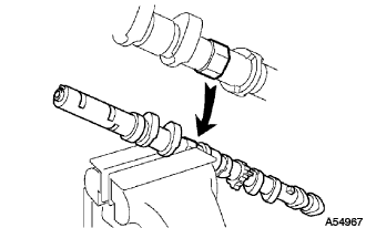
  1. Mount the hexagonal portion of the camshaft in a vise.

    NOTICE:
    Be careful not to damage the camshaft.


    A054962E02
  1. Align the camshaft knock pin with the knock pin groove of the timing tube, and push the timing tube by hand until it touches the bottom.

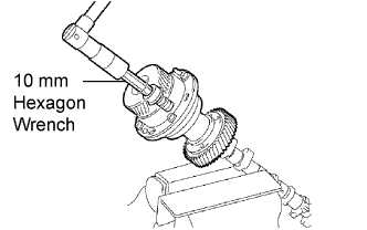
  1. Using a 10 mm hexagon wrench, install the bolt.

    Torque:
    78 N*m{ 795 kgf*cm , 58 ft.*lbf }

  1. Install the seal washer and screw plug.

    Torque:
    15 N*m{ 152 kgf*cm , 11 ft.*lbf }


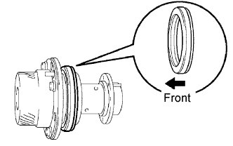
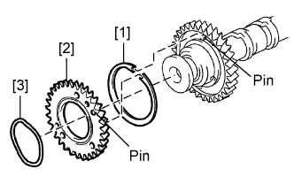
22. INSTALL CAMSHAFT SUB GEAR


    A054971E01
  1. Install the gear spring [1], sub gear [2] and wave washer [3].

    HINT:
    Attach the pins on the gears to the gear spring ends.


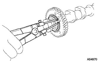
    A054970
  1. Using snap ring pliers, install the snap ring.


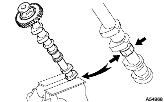
    A054968
  1. Mount the hexagonal portion of the camshaft in a vise.

    NOTICE:
    Be careful not to damage the camshaft.


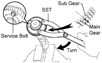
    A054972E01
  1. Using SST, align the holes of the driven main gear and sub gear by turning the sub gear clockwise, and temporarily install a service bolt.

    SST
    09960-10010   (09962-01000, 09963-00500)

  1. Align the gear teeth of the driven main gear and sub gear, and tighten the service bolt.
    Recommended service bolt: 
    Thread diameter
    6 mm
    Thread pitch
    1.0 mm
    Bolt length
    16 to 20 mm (0.63 to 0.79 in.)


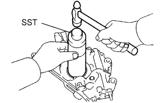
23. INSTALL OIL PUMP SEAL


    A054146E02
  1. Using SST and a hammer, tap in a new oil seal until its surface is flush with the oil pump body edge.

    SST
    09316-60011   (09316-00011)

  1. Apply MP grease to the oil seal lip.


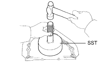
24. INSTALL ENGINE REAR OIL SEAL


    A054148E02
  1. Using SST and a hammer, tap in a new oil seal until its surface is flush with the rear oil seal retainer edge.

    SST
    09223-56010  

  1. Apply MP grease to the oil seal lip.


25. INSTALL ENGINE REAR OIL SEAL RETAINER
  1. Remove any old packing (FIPG) material and be careful not to drop any oil on the contact surfaces of the oil seal retainer and cylinder block.

    1. Using a razor blade and gasket scraper, remove all the oil packing (FIPG) material from the gasket surfaces and sealing grooves.

    2. Thoroughly clean all components to remove all the loose material.

    3. Using a non-residue solvent, clean both sealing surfaces.


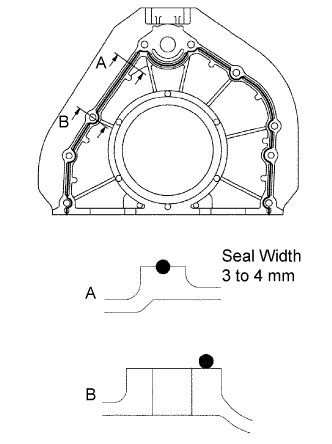
    A004848E02
  1. Apply seal packing to the oil seal retainer as shown in the illustration.

    Seal packing:
    Part No. 08826-00080 or equivalent


    1. Use a nozzle that has been cut to a 3 to 4 mm (0.12 to 0.16 in.) opening.

    2. Parts must be assembled within 5 minutes of application. Otherwise the material must be removed and reapplied.

    3. Immediately remove the nozzle from the tube and reinstall the cap.


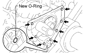
    A004855E02
  1. Install a new O-ring to the cylinder block.

  1. Install the oil seal retainer with the 7 bolts.

    Torque:
    8.0 N*m{ 82 kgf*cm , 71 in.*lbf }


26. INSTALL OIL PUMP ASSEMBLY


    B000960E03
  1. Remove any old packing (FIPG) material and be careful not to drop any oil on the contact surfaces of the oil pump and cylinder block.

    1. Using a razor blade and gasket scraper, remove all the old packing (FIPG) material from the gasket surfaces and sealing groove.

    2. Thoroughly clean all components to remove all the loose material.

    3. Using a non-residue solvent, clean both sealing surfaces.

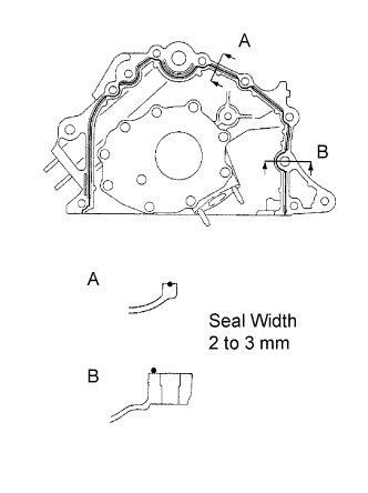
  1. Apply seal packing to the oil pump as shown in the illustration.

    Seal packing:
    Part No. 08826-00080 or equivalent

    NOTICE:
    Avoid applying an excessive amount to the surface, especially around the oil passage.


    1. Use a nozzle that has been cut to a 2 to 3 mm (0.08 to 0.12 in.) opening.

    2. Parts must be assembled within 5 minutes of application. Otherwise the material must be removed and reapplied.

    3. Immediately remove the nozzle from the tube and reinstall the cap.


    P021388E01
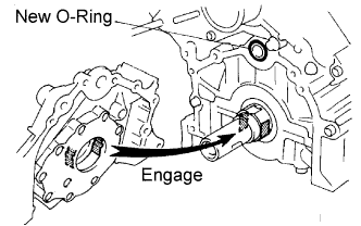
  1. Install a new O-ring to the cylinder block.

  1. Engage the spline teeth of the oil pump drive gear with the large teeth of the crankshaft, and slide the oil pump on the crankshaft.


    B013038E04
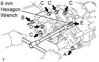
  1. Install the oil pump with a new stud bolt and the 7 bolts. Uniformly tighten the bolts diagonally.

    HINT:
    1. Use a 6mm hexagon wrench to tighten the hexagon head bolt.
    2. The following chart is the reference of the oil pump bolt length.
    Bolt
    Size of Bolt Head
    Length
    A
    12 mm
    50 mm (1.97 in.)
    B
    14 mm Stud Bolt
    102.8 mm (4.047 in.)
    C
    12 mm
    35 mm (1.38 in.)
    D
    14 mm
    44 mm (1.73 in.)
    E
    6 mm Hexagon
    28 mm (1.10 in.)

    Torque:
    For bolts A, B, C and E:
    16 N*m{ 160 kgf*cm , 11 ft.*lbf }
    For bolt D:
    31 N*m{ 311 kgf*cm , 23 ft.*lbf }


27. INSTALL OIL STRAINER SUB-ASSEMBLY


    A072708
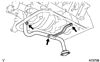
  1. Install a new gasket and the oil strainer with the 2 bolts and 2 nuts.

    Torque:
    7.5 N*m{ 76 kgf*cm , 66 in.*lbf }

    HINT:
    Use bolts 12 mm (0.47 in.) in length.


28. INSTALL STUD BOLT


  1. Install the stud bolt.


    A072716E01

    Torque:
    3.5 N*m{ 36 kgf*cm , 31 in.*lbf }


29. INSTALL OIL PAN SUB-ASSEMBLY


    A072709E01
  1. Remove any old packing (FIPG) material and be careful not to drop any oil on the contact surfaces of the No. 1 oil pan, cylinder block, oil pump and rear oil seal retainer.

    1. Using a razor blade and gasket scraper, remove all the old packing (FIPG) material from the gasket surfaces and sealing groove.
    2. Thoroughly clean all components to remove all the loose material.
    3. Using a non-residue solvent, clean both sealing surfaces.

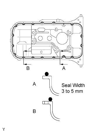
  1. Apply seal packing to the No. 1 oil pan as shown in the illustration.

    Seal packing:
    Part No. 08826-00080 or equivalent

    1. Use a nozzle that has been cut to a 3 to 5 mm (0.12 to 0.20 in.) opening.
    2. Parts must be assembled within 5 minutes of application. Otherwise the material must be removed and reapplied.
    3. Immediately remove the nozzle from the tube and reinstall the cap.


    A072710E01
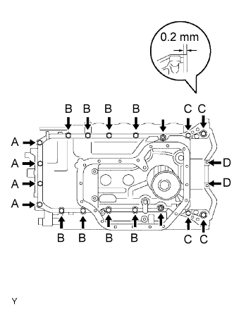
  1. Temporarily install the oil pan with the 18 bolts and 2 nuts.

    HINT:
    The following chart is the reference for the oil pump bolt length.

    Bolt
    Size of Bolt Head
    Length
    A
    10 mm
    20 mm (0.79 in.)
    B
    12 mm
    25 mm (0.98 in.)
    C
    12 mm
    60 mm (2.36 in.)
    D
    10 mm
    35 mm (1.38 in.)

  1. Set the oil pan as shown in the illustration.

    NOTICE:
    Make sure that the clearance between the rear end of the oil pan and cylinder block is 0.2 mm (0.008 in.) or less.
    If the clearance is more than 0.2 mm (0.008 in.), the oil pan will be stretched.

  1. Uniformly tighten the bolts and nuts diagonally.

    Torque:
    For bolts A and D:
    7.5 N*m{ 76 kgf*cm , 66 in.*lbf }
    For bolts B, C and nut:
    28 N*m{ 286 kgf*cm , 21 ft.*lbf }


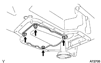
30. INSTALL OIL PAN BAFFLE PLATE


    A072705
  1. Install the baffle plate with the 2 bolts and 2 nuts.

    Torque:
    7.5 N*m{ 76 kgf*cm , 66 in.*lbf }

    HINT:
    Use bolts 12 mm (0.47 in.) in length.


31. INSTALL NO. 2 OIL PAN SUB-ASSEMBLY


    A072711E01
  1. Remove any oil packing (FIPG) material and be careful not to drop any oil on the contact surfaces of the No. 1 and No. 2 oil pans.

    1. Using a razor blade and gasket scraper, remove all the old packing (FIPG) material from the gasket surfaces and sealing groove.
    2. Thoroughly clean all components to remove all the loose material.
    3. Using a non-residue solvent, clean both sealing surfaces.

    NOTICE:
    Do not use a solvent which will affect the painted surfaces.

  1. Apply seal packing to the No. 2 oil pan as shown in the illustration.

    Seal packing:
    Part No. 08826-00080 or equivalent

    1. Use a nozzle that has been cut to a 3 to 5 mm (0.12 to 0.20 in.) opening.
    2. Parts must be assembled within 5 minutes of application. Otherwise the material must be removed and reapplied.
    3. Immediately remove the nozzle from the tube and reinstall the cap.

  1. Install the No. 2 oil pan with the 17 bolts and 2 nuts. Uniformly tighten the bolts and nuts in several steps.

    Torque:
    7.5 N*m{ 76 kgf*cm , 66 in.*lbf }

    HINT:
    Use bolts 14 mm (0.55 in.) in length.


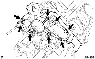
32. INSTALL WATER PUMP ASSEMBLY


    A054358
  1. Install a new gasket and water pump with the 5 bolts, 2 stud bolts and nut. Uniformly tighten the bolts, stud bolts and nut in several steps.

    Torque:
    Bolt:
    21 N*m{ 214 kgf*cm , 15 ft.*lbf }
    Stud bolt and nut:
    18 N*m{ 184 kgf*cm , 13 ft.*lbf }

    HINT:
    Use bolts 35 mm (1.38 in.) in length.


33. INSTALL CYLINDER HEAD SUB-ASSEMBLY


    A134378E01
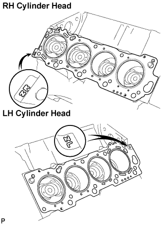
  1. Place 2 new cylinder head gaskets in position on the cylinder block.

    HINT:
    A mark is placed on the rear side of the cylinder head gasket to distinguish the LH and RH banks, a "2R" mark for the RH bank and a "2L" mark for the LH bank.

    NOTICE:
    Be careful of the installation direction.

  1. Place the 2 cylinder heads in position on the cylinder head gaskets.


    A072703E02
  1. Install the cylinder head bolts.

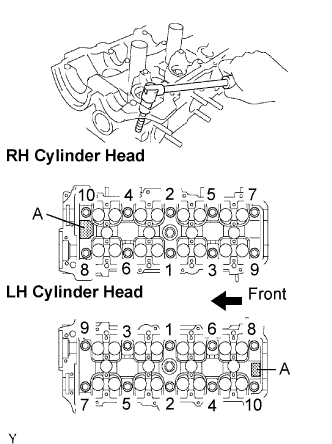
    HINT:
    1. The cylinder head bolts are tightened in 2 progressive steps (Procedures "A" and "B").
    2. If any cylinder head bolt is broken or deformed, replace it.


    1. Apply a light coat of engine oil on the threads and under the heads of the cylinder head bolts.

    2. Install the plate washer to the cylinder head bolt.

    3. Install and uniformly tighten the 10 cylinder head bolts on one side of the cylinder head in several steps in the order shown in the illustration, then do the other side in the same way (Procedure "A").

      Torque:
      40 N*m{ 408 kgf*cm , 30 ft.*lbf }

      If any one of the cylinder head bolts does not meet the torque specification, replace the cylinder head bolt.

      NOTICE:
      Do not drop the plate washer for the cylinder head bolt into portion A of the cylinder head. If dropped into portion A, the plate washer will pass through the cylinder head and cylinder block into the oil pan.


    4. A011159E01
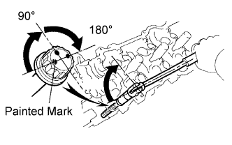
    5. Mark the front of the cylinder head bolt head with paint.

    6. Retighten the cylinder head bolts by 90° in the numerical order shown (Procedure "B").

    7. Retighten the cylinder head bolts by an additional 90°.

    8. Check that the painted mark is now at a 180° angle to front.


34. INSTALL CAMSHAFTS

NOTICE:
Since the thrust clearance of the camshaft is small, the camshaft must be kept level while it is being installed. If the camshaft is not kept level, the portion of the cylinder head which receives the shaft thrust may crack or be damaged, causing the camshaft to seize or break. To avoid this, the following steps should be carried out.


    A054460E01
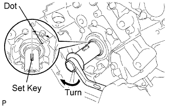
  1. Set the crankshaft position.

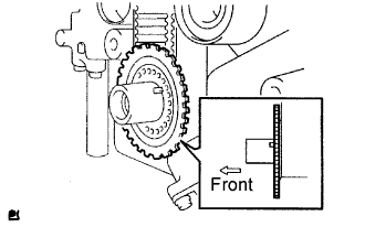
    1. Using the crankshaft damper bolt, turn the crankshaft, and set the set key of the crankshaft at the position of 90° counterclockwise from the timing mark (dot) of the oil pump body.

      CAUTION:
      Having the crankshaft at a wrong angle can cause the piston head and valve head to come into contact with each other when installing the camshaft, causing damage. So always set the crankshaft at the correct angle.


    A054974E01
  1. Install the camshafts of the RH bank.

    1. Apply engine oil to the thrust portions of the intake and exhaust camshafts.

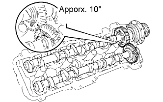
    2. Align the timing marks (1-dot mark) of the camshaft drive and driven main gears, and place the 2 camshafts.

    3. Set the timing marks (1-dot mark) of the camshaft drive and driven main gears at approx. 10° angle.


    4. A054975E02
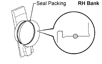
    5. Apply seal packing to the camshaft housing plug.

      1. Remove the old packing (FIPG) material.
      2. Apply seal packing to the housing plug.

      Seal packing:
      Part No. 08826-00080 or equivalent


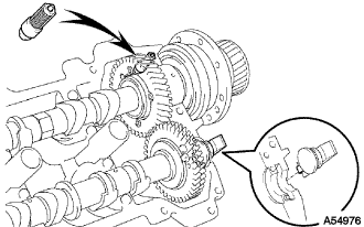
    6. A054976
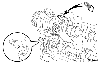
    7. Install the camshaft housing plug and oil control valve filter to the cylinder head as shown in the illustration.

      NOTICE:
      Be careful of the installation direction.


    8. A072712E01
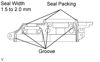
    9. Apply seal packing to the front bearing cap.

      1. Remove any old packing (FIPG) material and be careful not to drop any oil on the contact surfaces of the bearing cap and cylinder head.
        Using a razor blade and gasket scraper, remove all the old packing (FIPG) material from the gasket surfaces and groove.
        Thoroughly clean all components to remove all the loose material.
        Using a non-residue solvent, clean both sealing surfaces.
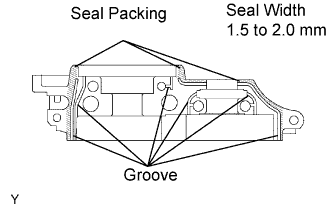
      2. Apply seal packing to the bearing cap as shown in the illustration.
        Use a nozzle that has been cut to 1.5 to 2.0 mm (0.059 to 0.079 in.) opening.
        Parts must be assembled within 5 minutes of application. Otherwise the material must be removed and reapplied.
        Immediately remove the nozzle from the tube and reinstall the cap.

      Seal packing:
      Part No. 08826-00080 or equivalent

      NOTICE:
      Do not apply seal packing to the front bearing cap grooves.


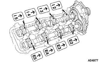
    10. A054977
    11. Install the front bearing cap.

      HINT:
      The thrust position of the camshaft will be determined after installing the front bearing cap.

    12. Install the other bearing caps in the order shown with the arrow mark facing forward.


    13. A054978E01
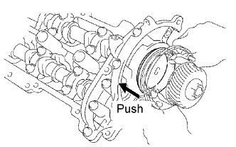
    14. Push in the camshaft setting oil seal.


    15. A004469E01
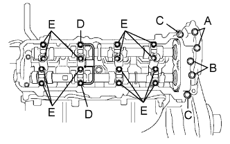
    16. Install new seal washers to the bearing cap bolts (A and B).

    17. Apply a light coat of engine oil to the threads and under the heads of the bearing cap bolts (D and E).

      NOTICE:
      Do not apply engine oil under the heads of the bearing cap bolts (A), (B) and (C).

      HINT:
      Each bolt length is as follows:
      94 mm (3.70 in.) for A with seal washer
      72 mm (2.83 in.) for B with seal washer
      25 mm (0.98 in.) for C
      55 mm (2.17 in.) for D
      40 mm (1.57 in.) for E

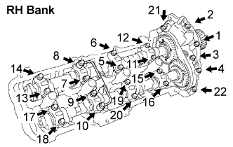
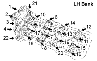
    18. Install the oil feed pipe and the 22 bearing cap bolts as shown in the illustration.


    19. A054151E05
    20. Uniformly tighten the 22 bearing cap bolts in several steps, in the order shown in the illustration.

      Torque:
      For bolt C:
      7.5 N*m{ 76 kgf*cm , 66 in.*lbf }
      For others:
      16 N*m{ 163 kgf*cm , 12 ft.*lbf }


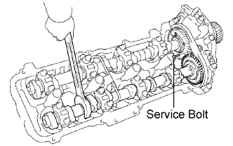
    21. A054149E01
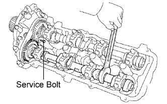
    22. Bring the service bolt installed in the driven sub-gear upward by turning the hexagonal portion of the camshaft with a wrench.

    23. Remove the service bolt.


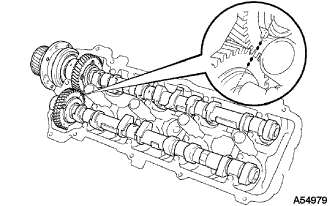
    A054979
  1. Install the camshafts of the LH bank.

    1. Apply MP grease to the thrust portion of the camshafts.

    2. Align the timing marks (2-dot marks) of the camshaft drive and driven main gears, and place the 2 camshafts.


    3. A054975E03
    4. Apply seal packing to the camshaft housing plug.

      1. Remove the old packing (FIPG) material.
      2. Apply seal packing to the housing plug.

      Seal packing:
      Part No. 08826-00080 or equivalent


    5. B002649
    6. Install the camshaft housing plug and oil control valve filter to the cylinder head as shown in the illustration.

      CAUTION:
      Be careful of the installation direction.


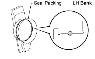
    7. A072713E01
    8. Apply seal packing to the front bearing cap.

      1. Remove any old packing (FIPG) material and be careful not to drop any oil on the contact surfaces of the bearing cap and cylinder head.
        Using a razor blade and gasket scraper, remove all the old packing (FIPG) material from the gasket surfaces and groove.
        Thoroughly clean all components to remove all the loose material.
        Using a non-residue solvent, clean both sealing surfaces.
      2. Apply seal packing to the bearing cap as shown in the illustration.
        Use a nozzle that has been cut to 1.5 to 2.0 mm (0.059 to 0.079 in.) opening.
        Parts must be assembled within 5 minutes of application. Otherwise the material must be removed and reapplied.
        Immediately remove the nozzle from the tube and reinstall the cap.

      Seal packing:
      Part No. 08826-00080 or equivalent

      NOTICE:
      Do not apply seal packing to the front bearing cap grooves.


    9. A054981
    10. Install the front bearing cap.

      HINT:
      The thrust position of the camshaft will be determined after installing the front bearing cap.

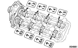
    11. Install the other bearing cap in the order shown with the arrow mark facing forward.


    12. A054982E01
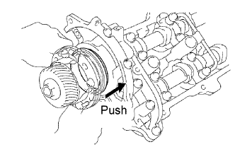
    13. Push in the camshaft setting oil seal.


    14. A054154E03
    15. Install a new seal washer to the bearing cap bolts (A and B).

    16. Apply a light coat of engine oil to the threads and under the heads of the bearing cap bolts (D and E).

      NOTICE:
      Do not apply engine oil under the heads of the bearing cap bolts (A), (B) and (C).

      HINT:
      Each bolt length is as follows:
      94 mm (3.70 in.) for A with seal washer
      72 mm (2.83 in.) for B with seal washer
      25 mm (0.98 in.) for C
      55 mm (2.17 in.) for D
      40 mm (1.57 in.) for E

    17. Install the oil feed pipe and the 22 bearing cap bolts as shown in the illustration.


    18. A054154E05
    19. Uniformly tighten the 22 bearing cap bolts in several steps, in the order shown in the illustration.

      Torque:
      For bolt C:
      7.5 N*m{ 76 kgf*cm , 66 in.*lbf }
      For others:
      16 N*m{ 163 kgf*cm , 12 ft.*lbf }


    20. A054152E01
    21. Bring the service bolt installed in the driven sub-gear upward by turning the hexagonal portion of the camshaft with a wrench.

    22. Remove the service bolt.


35. INSTALL REAR TIMING BELT PLATE RH
  1. Install the rear timing belt plate with the bolt and stud bolt.

    Torque:
    7.5 N*m{ 80 kgf*cm , 66 in.*lbf }


36. INSTALL NO. 2 REAR TIMING BELT PLATE RH
  1. Install the rear timing belt plate with the 2 bolts.

    Torque:
    7.5 N*m{ 80 kgf*cm , 66 in.*lbf }


37. INSTALL REAR TIMING BELT PLATE LH
  1. Install the rear timing belt plate with the bolt.
    Torque:
    7.5 N*m{ 80 kgf*cm , 66 in.*lbf }


38. INSTALL NO. 2 REAR TIMING BELT PLATE LH
  1. Install the rear timing belt plate with the 2 bolts.

    Torque:
    7.5 N*m{ 80 kgf*cm , 66 in.*lbf }


39. INSTALL CRANKSHAFT TIMING PULLEY


    A004446E01
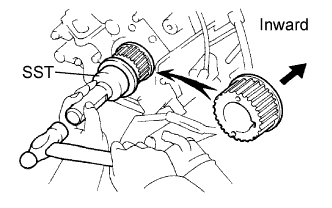
  1. Fit the timing pulley set key to the key groove of the pulley.

  1. Using SST and a hammer, tap in the timing pulley with the flange side facing inward.

    SST
    09223-46011  


40. INSTALL NO. 2 TIMING BELT IDLER SUB-ASSEMBLY


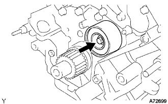
    A072699
  1. Install the idler with the bolt.
    Torque:
    35 N*m{ 352 kgf*cm , 25 ft.*lbf }

  1. Check that the idler moves smoothly.


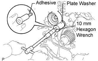
41. INSTALL NO. 1 TIMING BELT IDLER SUB-ASSEMBLY


    A054472E02
  1. Apply adhesive to 2 or 3 threads of the pivot bolt.
    Adhesive:
    Part No. 08833-00080, THREE BOND 1344, LOCTITE 242 or equivalent

  1. Using a 10 mm hexagon wrench, install the plate washer and idler with the pivot bolt.
    Torque:
    35 N*m{ 352 kgf*cm , 25 ft.*lbf }

  1. Check that the idler bracket moves smoothly.


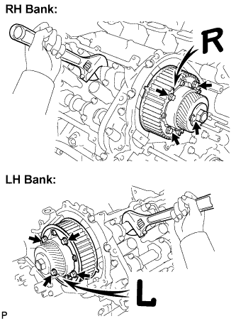
42. INSTALL CAMSHAFT TIMING PULLEYS


    A134379E01
  1. Align the camshaft timing tube knock pin with the knock pin groove of the timing pulley.

  1. Attach the timing pulley to the camshaft timing tube. Face the timing pulley's "R" and "L" marks forward.

  1. Hold the hexagonal portion of the camshaft.

  1. Using a 5 mm hexagon wrench, install the 8 bolts.

    Torque:
    8.1 N*m{ 83 kgf*cm , 72 in.*lbf }


43. INSTALL TIMING BELT

NOTICE:
The engine should be cold.


    A139504E01
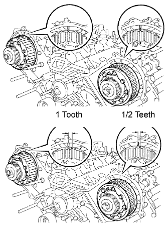
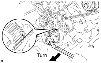
  1. Set the No. 1 cylinder to TDC/compression.

    1. Turn the hexagonal portion of the camshaft to align the timing marks of the camshaft timing pulleys and timing belt plates.

      HINT:
      By turning the camshaft timing pulleys clockwise as follows, installation of the timing pulleys will be easy:
      1/2 teeth turn for the left bank camshaft timing pulley
      1 tooth turn for the right bank camshaft timing pulley


    2. A054465E01
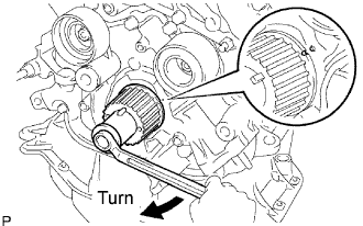
    3. Using the crankshaft damper bolt, turn the crankshaft to align the timing marks of the crankshaft timing pulley and oil pump body.


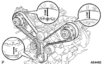
    A054463
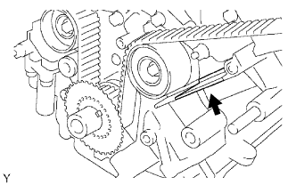
  1. Install the timing belt.
    1. Remove any oil or water on each pulley. Keep them clean after removal.

      NOTICE:
      Only wipe the pulleys; do not use any cleansing agent.
    2. Face the front mark (arrow) on the timing belt forward.
    3. Connect the timing belt to the crankshaft timing pulley.

      1. Align the installation mark on the timing belt with the timing mark of the crankshaft timing pulley.

    4. Connect the No. 2 timing belt to the idler.

    5. Connect the timing belt to the camshaft timing pulley LH.

      1. Align the installation mark on the timing belt with the timing mark of the camshaft timing pulley.

    6. Connect the timing belt to the water pump pulley.

    7. Connect the timing belt to the camshaft timing pulley (RH bank).

      1. Align the installation mark on the timing belt with the timing mark of the camshaft timing pulley.

    8. Connect the No. 1 timing belt to the idler.


    A054983E02
  1. Set the belt tensioner.

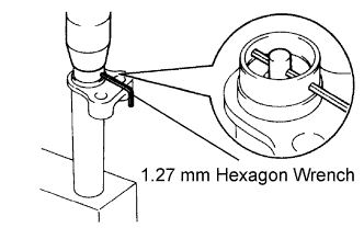
    1. Using a press, slowly press in the push rod using 981 to 9,807 N (100 to 1,000 kgf, 220 to 2,205 lbf) of pressure.

    2. Align the holes of the push rod and housing, pass a 1.27 mm hexagon wrench through the holes to keep the setting position of the push rod.

    3. Release the press.

    4. Install the dust boot to the belt tensioner.


    A054462E02
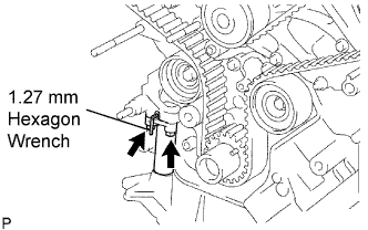
  1. Install the belt tensioner.

    1. Temporarily install the belt tensioner with the 2 bolts.

    2. Alternately tighten the 2 bolts.

      Torque:
      26 N*m{ 270 kgf*cm , 19 ft.*lbf }

    3. Using pliers, remove the 1.27 mm hexagon wrench from the belt tensioner.


    A054456E01
  1. Check the valve timing.

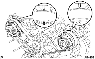
    1. Using the crankshaft damper bolt, slowly turn the crankshaft pulley 2 revolutions from the TDC to TDC.

      NOTICE:
      Always turn the crankshaft pulley clockwise.


    2. A054458
    3. Check that each pulley aligns with the timing marks as shown in the illustration.
      If the timing marks are not aligned, remove the timing belt and reinstall it.


44. INSTALL NO. 1 CRANKSHAFT POSITION SENSOR PLATE


    A053994E01
  1. Install the sensor plate as shown in the illustration.

    NOTICE:
    Take care not to install it in a wrong direction.


45. INSTALL TIMING GEAR COVER SPACER


    A072695E01
  1. Install the gasket to the cover spacer.

  1. Install the cover spacer.


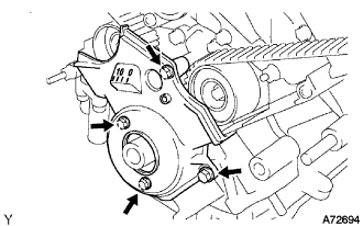
46. INSTALL NO. 1 TIMING BELT COVER


    A072694
  1. Install the timing belt cover with the 4 bolts.

    Torque:
    7.5 N*m{ 80 kgf*cm , 66 in.*lbf }


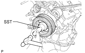
47. INSTALL CRANKSHAFT DAMPER SUB-ASSEMBLY


    A054471E02
  1. Align the pulley set key with the key groove of the crankshaft damper.

  1. Using SST and a hammer, tap in the crankshaft damper.

    SST
    09223-46011  


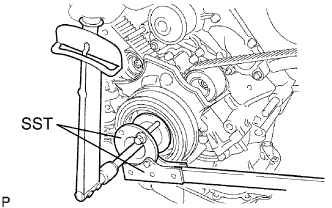
    A054469E02
  1. Using SST, install the damper bolt.

    SST
    09213-70011   (90105-08076)
    09330-00021  

    Torque:
    245 N*m{ 2,498 kgf*cm , 181 ft.*lbf }


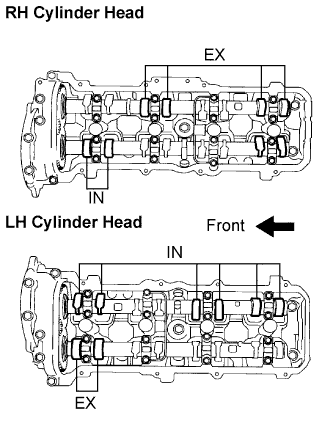
48. INSPECT VALVE CLEARANCE


    A005717E03
  1. Check only the valves indicated.

    1. Using a feeler gauge, measure the clearance between the valve lifter and camshaft.

    2. Record the out-of-specification valve clearance measurements. They will be used later to determine the required replacement adjusting shim.

      Valve clearance (Cold):
      Intake:
      0.15 to 0.25 mm (0.006 to 0.010 in.)
      Exhaust:
      0.25 to 0.35 mm (0.010 to 0.014 in.)


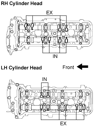
    A004457E03
  1. Turn the crankshaft 1 complete revolution (360°) and align the camshaft timing marks.

  1. Check only the valves indicated as shown in the illustration. Measure the valve clearance.


49. ADJUST VALVE CLEARANCE
  1. Remove the timing belt .

  1. Remove the camshafts (RH Bank) .

  1. Remove the camshafts (LH Bank) .

  1. Remove the valve lifter and adjusting shim.

    NOTICE:
    Be careful not to drop the adjusting shim into the cylinder head.


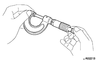
    A002213
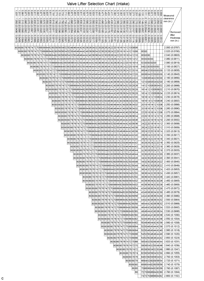
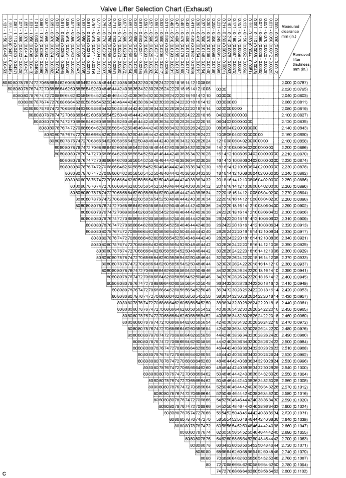
  1. Determine the replacement adjusting shim size according to the formula or charts on the following pages.

    1. Using a micrometer, measure the thickness of the removed shim.

    2. Calculate the thickness of a new shim so that the valve clearance comes within the specified value.

      T:
      Thickness of removed shim

      A:
      Measured valve clearance

      N:
      Thickness of new shim

      Intake:
      N = T + (A - 0.20 mm (0.008 in.))

      Exhaust:
      N = T + (A - 0.30 mm (0.012 in.))


    3. Select a new shim with a thickness as close as possible to the calculated value.

      HINT:
      1. Shims are available in 41 increments of 0.020 mm (0.0008 in.), from 2.00 mm (0.0787 in.) to 2.80 mm (0.1102 in.).
      2. Refer to the new adjusting shim thickness table on the next 2 pages.


      A134420


      A134421

  1. Place a new adjusting shim on the valve.

  1. Place the valve lifter.

  1. Reinstall the camshafts (LH Bank) .

  1. Reinstall the camshafts (RH Bank) .

  1. Reinstall the timing belt .

  1. Recheck the valve clearance.


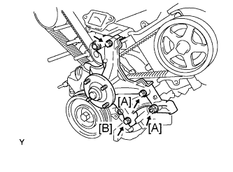
50. INSTALL FAN BRACKET SUB-ASSEMBLY


    A134365E04
  1. Install the idler pulley with the 2 bolts and 2 nuts.

    Torque:
    For 12 mm head:
    16 N*m{ 160 kgf*cm , 12 ft.*lbf }
    For 14 mm head:
    32 N*m{ 326 kgf*cm , 24 ft.*lbf }

    HINT:
    Each bolt length is as follows:
    106 mm (4.17 in.) for 12 mm head [A]
    114 mm (4.49 in.) for 14 mm head [B]


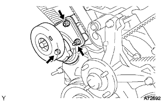
51. INSTALL V-RIBBED BELT TENSIONER ASSEMBLY


    A072692
  1. Install the belt tensioner with the bolt and 2 nuts.

    Torque:
    16 N*m{ 160 kgf*cm , 11 ft.*lbf }

    HINT:
    Use a bolt 106 mm (4.17 in.) in length.


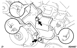
52. INSTALL NO. 2 TIMING BELT COVER SUB-ASSEMBLY


    A054467
  1. Install the timing belt cover and fit the claws and pins into each part.

  1. Install the timing belt cover with the 2 bolts.

    Torque:
    16 N*m{ 160 kgf*cm , 12 ft.*lbf }

    HINT:
    Use bolts 106 mm (4.17 in.) in length.


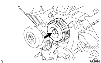
53. INSTALL NO. 2 IDLER PULLEY SUB-ASSEMBLY


    A072691
  1. Install the idler pulley and cover plate with the bolt.
    Torque:
    39 N*m{ 398 kgf*cm , 29 ft.*lbf }


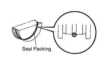
54. INSTALL SEMICIRCULAR PLUG


    A054984E02
  1. Remove any old packing (FIPG) material.

  1. Apply seal packing to the semicircular plug grooves.

    Seal packing:
    Part No. 08826-00080 or equivalent


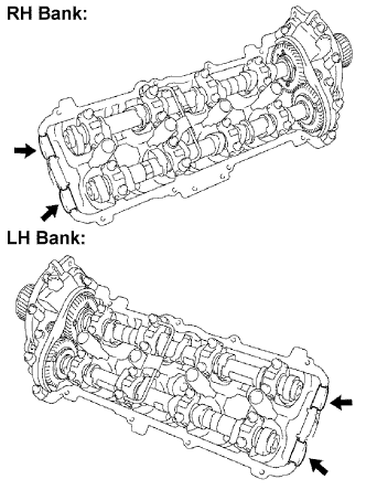
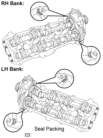
    A054985E02
  1. Install the 4 semicircular plugs to the cylinder heads as shown in the illustration.


55. INSTALL CYLINDER HEAD COVER


    A054067E02
  1. Remove any old packing (FIPG) material.

  1. Apply seal packing to the cylinder heads as shown in the illustration.

    Seal packing:
    Part No. 08826-00080 or equivalent

  1. Install the gasket to the cylinder head cover.

  1. Install the seal washer to the bolt.
  1. Install the cylinder head cover with the 9 bolts. Uniformly tighten the bolts in several steps.
    Torque:
    6.0 N*m{ 60 kgf*cm , 53 in.*lbf }


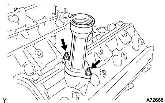
56. INSTALL OIL FILLER CAP HOUSING


    A072688
  1. Install a new gasket and the oil filler cap housing with the 2 nuts.

    Torque:
    7.5 N*m{ 76 kgf*cm , 66 in.*lbf }


57. INSTALL OIL FILLER CAP SUB-ASSEMBLY


58. INSTALL SPARK PLUG

Torque:
18 N*m{ 178 kgf*cm , 13 ft.*lbf }


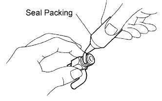
59. INSTALL CYLINDER BLOCK WATER DRAIN COCK SUB-ASSEMBLY


    P012477E01
  1. Apply seal packing to 2 or 3 threads.

    Seal packing:
    Part No. 08826-00100 or equivalent


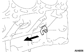
    A004856
  1. Install the 2 drain cocks.

    Torque:
    49 N*m{ 500 kgf*cm , 36 ft.*lbf }

    HINT:
    After tightening to the specified torque, rotate the drain union clockwise until its drain port is facing forward.


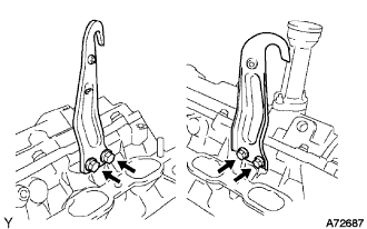
60. INSTALL ENGINE HANGERS


    A072687
  1. Install the 2 engine hangers with the 4 bolts.

    Torque:
    37 N*m{ 380 kgf*cm , 27 ft.*lbf }