 |
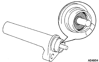
Visually check the seal portion of the tensioner for oil leakage.
- HINT:
- If there is a faint trace of oil on the seal on the push rod side, the tensioner is all right.
- If leakage is found, replace the tensioner.
ENGINE UNIT > INSPECTION |
| 1. INSPECT TIMING BELT |
If premature parting occurs, check the following:
If the belt teeth are cracked or damaged, inspect the camshaft.
If there is noticeable wear or cracks on the belt face, check if there are nicks on the side of the idler pulley lock and water pump.
If there is wear or damage on only one side of the belt, check the belt guide and alignment of each pulley.
If there is noticeable wear on the belt teeth, check for damage on the timing belt or foreign objects on the pulley teeth. Check if the gasket is installed correctly.
If necessary, replace the timing belt.
| 2. INSPECT NO. 1 CHAIN TENSIONER ASSEMBLY |
|
Visually check the seal portion of the tensioner for oil leakage.
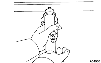 |
Hold the tensioner by hands and push the push rod strongly as shown in the illustration to check that it does not move.
If the push rod moves, replace the tensioner.
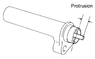 |
Measure the protrusion of the push rod from the housing end.
| 3. INSPECT TIMING BELT IDLER |
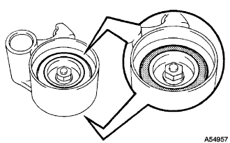 |
Visually check the seal portion of the idler pulley for oil leakage.
If leakage is found, replace the idler pulley.
Check that the idler pulley turns smoothly.
If necessary, replace the idler.
| 4. INSPECT CYLINDER HEAD SET BOLT |
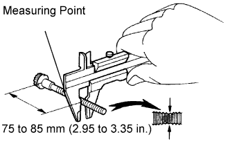 |
Using vernier calipers, measure the thread outside diameter of the bolt.
| 5. INSPECT CAMSHAFTS |
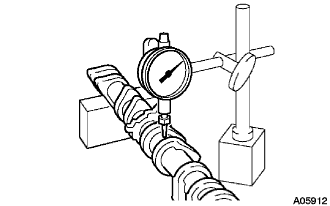 |
Inspect the camshaft for runout.
Place the camshaft on V-blocks.
Using a dial indicator, measure the circle runout at the center journal.
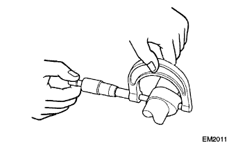 |
Inspect the cam lobes.
Using a micrometer, measure the cam lobe height.
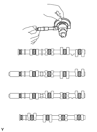 |
Inspect the camshaft journals.
Using a micrometer, measure the journal diameter.
| 6. INSPECT CAMSHAFT TIMING TUBE ASSEMBLY |
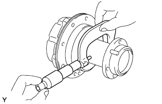 |
Using a micrometer, measure the journal diameter.
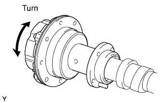 |
Install the timing tube to the intake camshaft, and check that the timing tube turns smoothly.
If necessary, replace the timing tube and intake camshaft.
| 7. INSPECT CAMSHAFT GEAR SPRING |
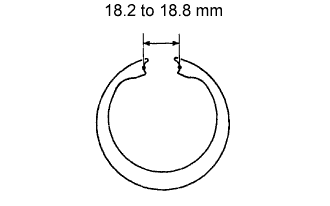 |
Using vernier calipers, measure the gap distance of the gear spring.
| 8. INSPECT CYLINDER HEAD SUB-ASSEMBLY |
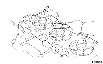 |
Clean the cylinder head.
Using a gasket scraper, remove all the gasket material from the cylinder block contact surface.
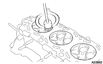 |
Using a wire brush, remove all the carbon from the combustion chambers.
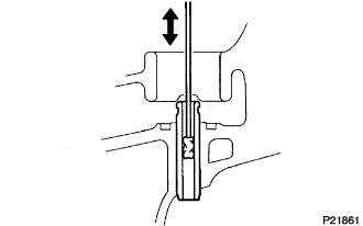 |
Using a valve guide bushing brush and solvent, clean all the guide bushes.
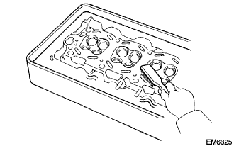 |
Using a soft brush and solvent, thoroughly clean the cylinder head.
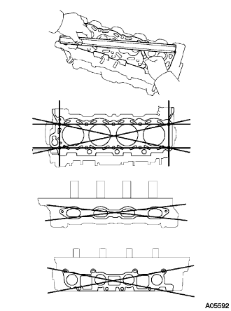 |
Inspect for warpage.
Using a precision straight edge and feeler gauge, measure the warpage of the contact surfaces of the cylinder block and the manifolds.
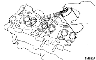 |
Inspect for cracks.
Using a dye penetrant, check the combustion chamber, intake ports, exhaust ports and cylinder block surface for cracks.
If cracked, replace the cylinder head.
| 9. INSPECT VALVE |
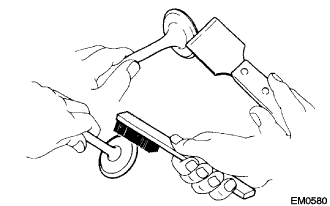 |
Clean the valves.
Using a gasket scraper, chip off any carbon from the valve head.
Using a wire brush, thoroughly clean the valve.
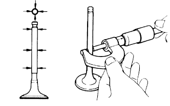 |
Using a micrometer, measure the diameter of the valve stem.
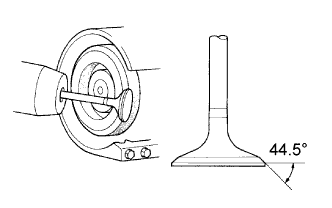 |
Check the valve face angle.
Grind the valve enough to remove pits and carbon.
Check that the valve is ground to the correct valve face angle.
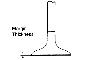 |
Check the valve head margin thickness.
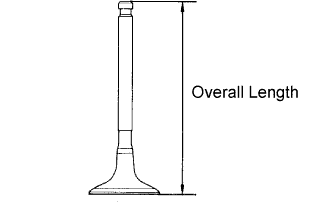 |
Check the valve overall length.
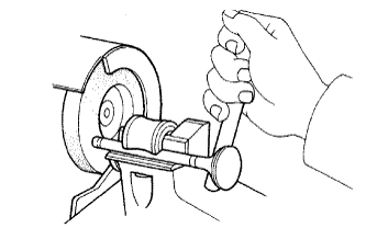 |
Check the surface of the valve stem tip for wear.
If the valve stem tip is worn, resurface the tip with a grinder or replace the valve.
| 10. INSPECT VALVE SPRING |
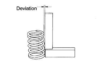 |
Using a steel square, measure the deviation of the valve spring.
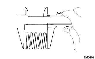 |
Using vernier calipers, measure the free length of the valve spring.
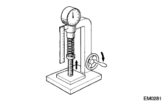 |
Using a spring tester, measure the tension of the valve spring at the specified installed length.
| 11. INSPECT VALVE GUIDE BUSH |
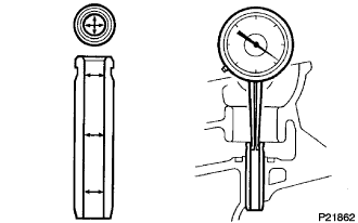 |
Using a caliper gauge, measure the inside diameter of the guide bush.
Subtract the valve stem diameter measurement from the guide bush inside diameter measurement.
| 12. REMOVE VALVE GUIDE BUSH |
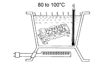 |
Gradually heat the cylinder head to 80 to 100°C (176 to 212°F).
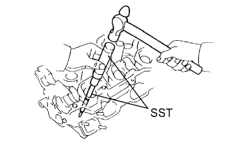 |
Using SST and a hammer, tap out the guide bush.
| 13. INSTALL VALVE GUIDE BUSH |
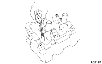 |
Using a caliper gauge, measure the bush bore diameter of the cylinder head.
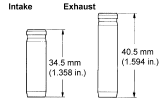 |
Select a new guide bush (STD or O/S 0.05).
| Bush bore diameter | Bush size |
| 10.285 to 10.306 mm (0.4049 to 0.4057 in.) | Use STD |
| 10.335 to 10.356 mm (0.4069 to 0.4077 in.) | Use O/S 0.05 |
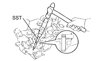 |
Gradually heat the cylinder head to 80 to 100°C (176 to 212°F).
Using SST and a hammer, tap in a new guide bush to the specified protrusion height.
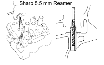 |
Using a sharp 5.5mm reamer, ream the guide bush to obtain the specified clearance between the guide bush and valve stem.
| 14. INSPECT VALVE SEAT |
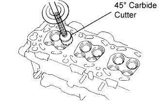 |
Using a 45° carbide cutter, resurface the valve seats. Clean metal filings from the valve seats.
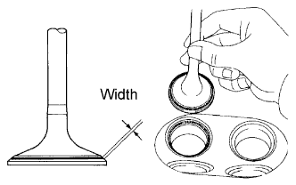 |
Check the valve seating position.
Apply a light coat of prussian blue (or white lead) to the valve face.
Lightly press the valve against the seat. Do not rotate valve.
Check the valve face and seat for the following:
If prussian blue appears around the entire face, the valve is centered. If not, replace the valve.
If prussian blue appears around the entire valve seat, the guide and face are centered. If not, resurface the seat.
Check that the seat contacts in the middle of the valve face with the following width:
| 15. REPAIR VALVE SEAT |
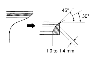 |
If the seating is too high on the valve face, use 30° and 45° cutters to correct the seat.
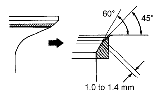 |
If the seating is too low on the valve face, use 60° and 45° cutters to correct the seat.
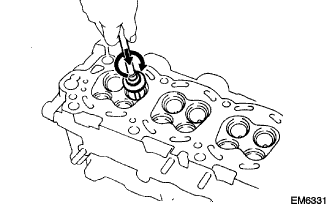 |
Handrub the valve and valve seat with an abrasive compound.
After handrubbing, clean the valve and valve seat.
| 16. INSPECT VALVE LIFTER |
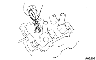 |
Using a caliper gauge, measure the lifter bore diameter of the cylinder head.
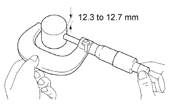 |
Using a micrometer, measure the lifter diameter where the distance from the top surface is 12.3 to 12.7 mm (0.484 to 0.500 in.).
Subtract the lifter diameter measurement from the lifter bore diameter measurement.
| 17. INSPECT CAMSHAFT OIL CLEARANCE |
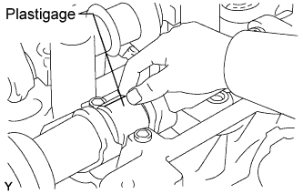 |
Install the camshaft timing tube to the camshaft .
Clean the bearing caps and camshaft journals.
Check the bearings for flaking and scoring.
If the bearings are damaged, replace the bearing caps and cylinder head as a set.
Place the camshafts on the cylinder head.
Lay a strip of Plastigage across each of the camshaft journals.
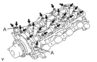 |
Install the bearing caps .
Remove the bearing caps.
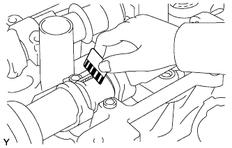 |
Measure the Plastigage at its widest point.
| Camshaft journal | Camshaft timing tube journal |
| 0.030 to 0.071 mm (0.0012 to 0.0028 in.) | 0.036 to 0.057 mm (0.0014 to 0.0022 in.) |
| Camshaft journal | Camshaft timing tube journal |
| 0.100 mm (0.0039 in.) | 0.075 mm (0.0030 in.) |
Remove the camshafts.
Completely remove the Plastigage.
| 18. INSPECT CAMSHAFT THRUST CLEARANCE |
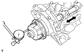 |
Install the camshaft .
Using a dial indicator, measure the thrust clearance while moving the camshaft back and forth.
| Intake | Exhaust |
| 0 to 0.040 mm (0 to 0.0016 in.) | 0.030 to 0.070 mm (0.0012 to 0.0028 in.) |
| Intake | Exhaust |
| 0.12 mm (0.0047 in.) | 0.10 mm (0.0039 in.) |
Remove the camshafts.
Remove the camshaft timing tube from the intake camshaft.
| 19. INSPECT CAMSHAFT GEAR BACKLASH |
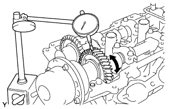 |
Install the drive gear to the camshaft timing tube .
Install the camshaft timing tube to the intake camshaft .
Install the camshafts without installing the exhaust camshaft sub-gear No. 3 and front bearing cap .
Using a dial indicator, measure the backlash.
Remove the camshafts.
Remove the camshaft timing tube from the intake camshaft.
Remove the drive gear from the camshaft timing tube.
| 20. CLEAN CYLINDER BLOCK SUB-ASSEMBLY |
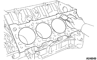 |
Using a gasket scraper, remove all the gasket material from the top surface of the cylinder block.
Using a soft brush and solvent, thoroughly clean the cylinder block.
| 21. INSPECT CYLINDER BLOCK SUB-ASSEMBLY |
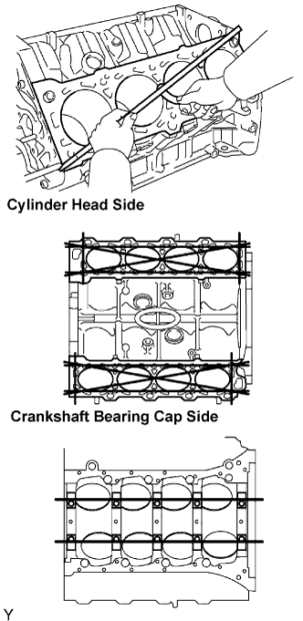 |
Inspect for warpage.
Using a precision straight edge and feeler gauge, measure the warpage of the contact surfaces of the cylinder head and crankshaft bearing cap.
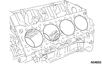 |
Visually check the cylinder for vertical scratches.
If deep scratches are present, rebore all the 8 cylinders and replace all the 8 pistons. If necessary, replace the cylinder block.
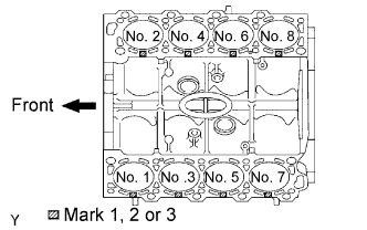 |
Inspect the cylinder bore diameter.
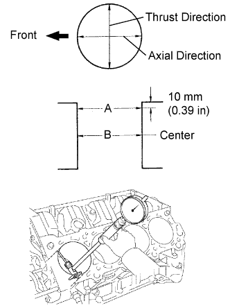 |
Using a cylinder gauge, measure the cylinder bore diameter at positions A and B in the thrust and axial directions.
| STD | ||
| Mark "1" | Mark "2" | Mark "3" |
| 94.002 to 94.010 mm (3.7009 to 3.7012 in.) | 94.010 to 94.023 mm (3.7012 to 3.7017 in.) | 94.023 to 94.031 mm (3.7017 to 3.7020 in.) |
| STD | 94.231 mm (3.7099 in.) |
| O/S 0.50 | 94.731 mm (3.7296 in.) |
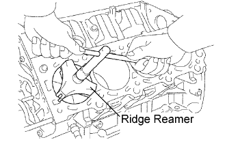 |
Remove the cylinder ridge.
If the wear is less than 0.2mm (0.008 in.), using a ridge reamer, grind the top of the cylinder.
| 22. INSPECT PISTON |
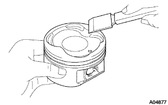 |
Clean the piston.
Using a gasket scraper, remove the carbon from the piston top.
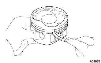 |
Using a groove cleaning tool or broken ring, clean the piston ring grooves.
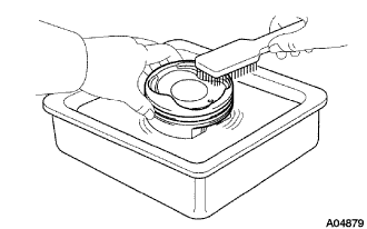 |
Using solvent and a brush, thoroughly clean the piston.
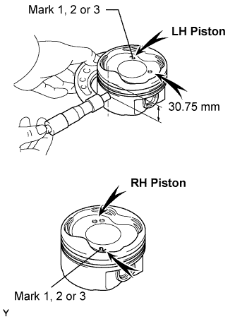 |
Inspect the piston oil clearance.
Using a micrometer, measure the piston diameter at right angles to the piston pin center line, 30.75 mm (1.2106 in.) from the piston head.
| O/S 0.50 | STD | ||
| Mark "1" | Mark "2" | Mark "3" | |
| 94.402 to 94.430 mm (3.7168 to 3.7177 in.) | 93.902 to 93.912 mm (3.6969 to 3.6973 in.) | 93.912 to 93.920 mm (3.6973 to 3.6976 in.) | 93.920 to 93.930 mm (3.6976 to 3.6980 in.) |
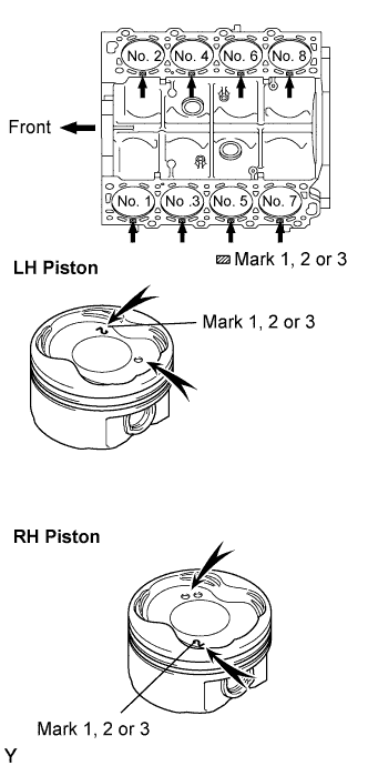 |
Measure the cylinder bore diameter in the thrust directions.
Subtract the piston diameter measurement from the cylinder bore diameter measurement.
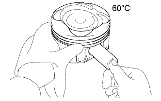 |
Inspect the piston pin fit.
Heat the piston to approx. 60° C (140° F), and push the piston pin into the piston pin hole with your thumb.
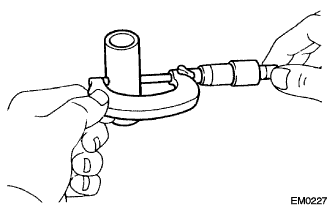 |
Using a micrometer, measure the piston pin diameter.
| 23. INSPECT PISTON RING SET |
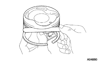 |
Inspect the piston ring groove clearance.
Using a feeler gauge, measure the clearance between the new piston ring and the wall of the ring groove.
| No. 1 | No. 2 |
| 0.030 to 0.080 mm (0.0012 to 0.0032 in.) | 0.020 to 0.060 mm (0.0008 to 0.0024 in.) |
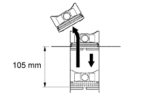 |
Inspect the piston ring end gap.
Insert the piston ring into the cylinder bore.
Using a piston, push the piston ring a little beyond the bottom of the ring travel, 105 mm (4.13 in.) from the top of the cylinder block.
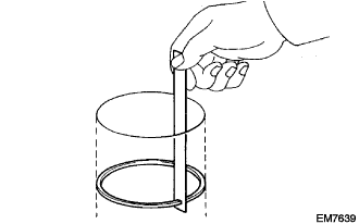 |
Using a feeler gauge, measure the end gap.
| No. 1 | No. 2 | Oil (Side rail) |
| 0.300 to 0.400 mm (0.0118 to 0.0158 in.) | 0.400 to 0.550 mm (0.0158 to 0.0217 in.) | 0.130 to 0.380 mm (0.0051 to 0.0150 in.) |
| No. 1 | No. 2 | Oil (Side rail) |
| 1.10 mm (0.0433 in.) | 1.30 mm (0.0512 in.) | 0.90 mm (0.0354 in.) |
| 24. INSPECT CONNECTING ROD SUB-ASSEMBLY |
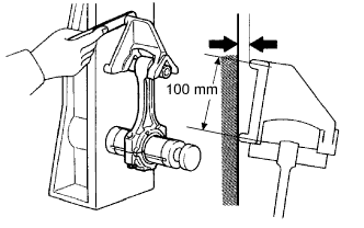 |
Using a rod aligner and feeler gauge, check the connecting rod alignment.
Check for bend.
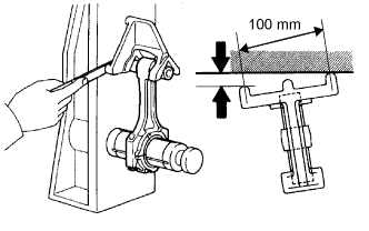 |
Check for twist.
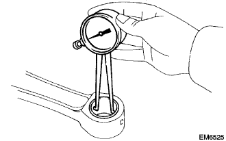 |
Inspect the piston pin oil clearance.
Using a caliper gauge, measure the inside diameter of the connecting rod bushing.
|
Using a micrometer, measure the piston pin diameter.
Subtract the piston pin diameter measurement from the bushing inside diameter measurement.
| 25. REMOVE CONNECTING ROD SMALL END BUSH |
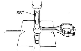 |
Using SST and a press, press out the bushing.
| 26. INSTALL CONNECTING ROD SMALL END BUSH |
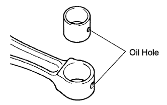 |
Align the oil holes of a new bushing and the connecting rod.
|
Using SST and a press, press in the bushing.
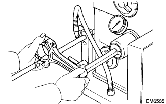 |
Using a pin hole grinder, hone the bushing to obtain the specified clearance between the bushing and piston pin.
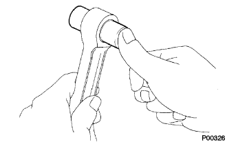 |
Check the piston pin fit at normal room temperature. Coat the piston pin with engine oil, and push it into the connecting rod with your thumb.
| 27. INSPECT CONNECTING ROD BOLT |
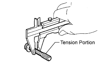 |
Using vernier calipers, measure the tension portion diameter of the connecting rod bolt.
| 28. INSPECT CRANKSHAFT BEARING CAP BOLT |
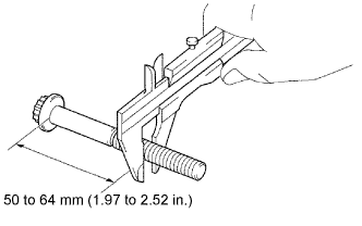 |
Using vernier calipers, measure the thread outside diameter of the crankshaft bearing cap bolt.
| 29. INSPECT CRANKSHAFT |
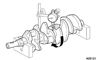 |
Inspect for circle runout.
Place the crankshaft on V-blocks.
Using a dial indicator, measure the circle runout at the center journal.
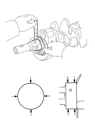 |
Inspect the crankshaft journals and crank pins.
Using a micrometer, measure the diameter of each crankshaft journal and crank pin.
Check each crankshaft journal and crank pin for taper and out-of-round as shown in the illustration.