CYLINDER HEAD > INSTALLATION |
| 1. INSTALL NO. 2 CYLINDER HEAD GASKET |
Remove any old packing (FIPG) material and be careful not to drop any oil on the contact surfaces of the cylinder head and cylinder block.
![]() |
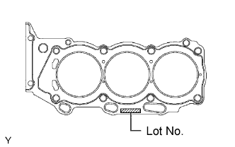
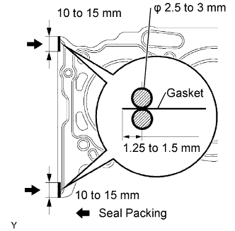
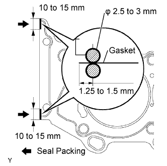
Apply seal packing (diameter: 2.5 to 3 mm (0.098 to 0.118 in.)) to a new cylinder head gasket as shown in the illustration.
![]() |
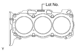
Place the cylinder head gasket on the cylinder block surface with the Lot No. stamp upper side facing upward.
| 2. INSTALL CYLINDER HEAD LH |
Place the cylinder head on the cylinder head gasket.
Install the 8 cylinder head bolts.
Apply a light coat of engine oil to the threads of the cylinder head bolts.
Install the plate washer to the cylinder head bolt.
![]() |
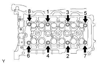
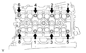
Using several steps, tighten each bolt uniformly with a 10 mm bi-hexagon wrench in the sequence as shown in the illustration (Procedure "A").
![]() |
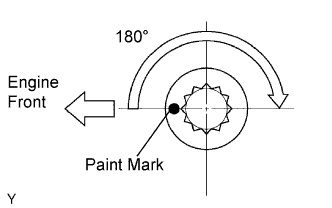
Mark the front side of each cylinder head bolt with paint.
Retighten the cylinder head bolts 180° as shown (Procedure "B").
Check that the painted marks are now at 180° opposite to the engine front.
![]() |
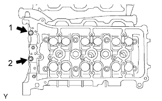
Install the 2 cylinder head bolts.
Apply a light coat of engine oil to the threads of the cylinder head bolts.
Using several steps, install and tighten the 2 cylinder head bolts uniformly in the sequence as shown in the illustration.
Install the ground cable with the bolt.
| 3. INSTALL CYLINDER HEAD GASKET |
Remove any old packing (FIPG) material and be careful not to drop any oil on the contact surfaces of the cylinder head and cylinder block.
![]() |
Apply seal packing (diameter: 2.5 to 3 mm (0.098 to 0.118 in.)) to a new cylinder head gasket as shown in the illustration.
![]() |
Place the cylinder head gasket on the cylinder block surface with the Lot No. stamp upper side facing upward.
| 4. INSTALL CYLINDER HEAD SUB-ASSEMBLY |
Place the cylinder head on the cylinder head gasket.
Install the 8 cylinder head bolts.
Apply a light coat of engine oil to the threads of the cylinder head bolts.
Install the plate washer to the cylinder head bolt.
![]() |
Using several steps, tighten each bolt uniformly with a 10 mm bi-hexagon wrench in the sequence as shown in the illustration (Procedure "A").
![]() |
Mark the front side of each cylinder head bolt with paint.
Retighten the cylinder head bolts 180° as shown (Procedure "B").
Check that the painted marks are now at 180° opposite to the engine front.
Install the ground cables with the 2 bolts.
| 5. INSTALL CAMSHAFTS (for Bank 2) |
![]() |
Set the crankshaft position.
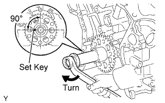
Install the crankshaft pulley set bolt, and turn the crankshaft, and set the crankshaft set key at the left horizontal position.
Apply new engine oil to the thrust portions and journals of the camshafts.
![]() |
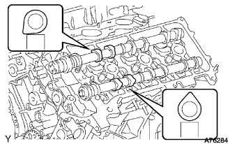
Place the 2 camshafts onto the cylinder head with the cam lobes of No. 2 cylinder facing each correct direction as shown in the illustration.
![]() |
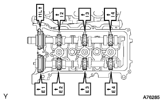
Install the 8 bearing caps in their proper locations.
Apply a light coat of engine oil to the threads and under the heads of the bearing cap bolts.
![]() |
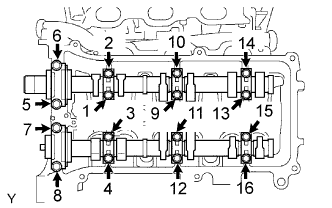
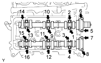
Using several steps, install and tighten the 16 bearing cap bolts uniformly in the sequence as shown in the illustration.
| 6. INSTALL NO. 3 CHAIN TENSIONER ASSEMBLY |
![]() |
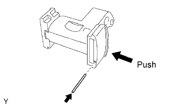
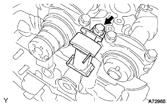
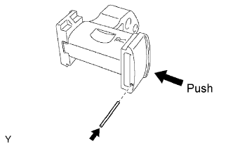
While pushing in the tensioner, insert a pin of φ1.0 mm (0.039 in.) into the hole to fix it.
![]() |
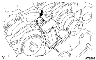
Install the No. 3 chain tensioner with the bolt.
| 7. INSTALL CAMSHAFT TIMING GEARS AND NO. 2 CHAIN (for Bank 2) |
![]() |
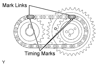
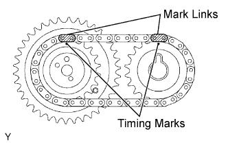
Align the mark links (yellow) with the timing marks (1-dot mark and 2-dot mark) of the camshaft timing gears as shown in the illustration.
![]() |
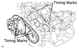
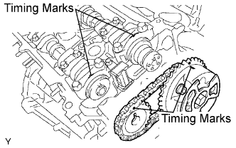
Align the timing marks on the camshaft timing gears with the timing marks on the bearing caps, and install the camshaft timing gears with the chain to the LH camshafts.
Temporarily install the 2 camshaft timing gear bolts.
![]() |
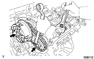
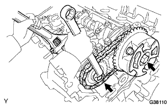
Hold the hexagonal portion of the camshaft with a wrench, and tighten the 2 bolts.
Remove the pin from the No. 3 tensioner.
| 8. INSTALL NO. 1 CHAIN VIBRATION DAMPER |
![]() |
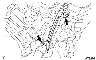
Install the No. 1 chain vibration damper with the 2 bolts.
| 9. INSTALL NO. 2 CAMSHAFT BEARING |
![]() |
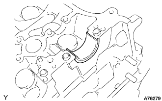
Install the No. 2 camshaft bearing to the cylinder head.
| 10. INSTALL CAMSHAFTS (for Bank 1) |
![]() |
Set the crankshaft position.
Using the crankshaft pulley set bolt, turn the crankshaft, and set the crankshaft set key into the left horizontal position.
Apply new engine oil to the thrust portions and journals of the camshafts.
![]() |
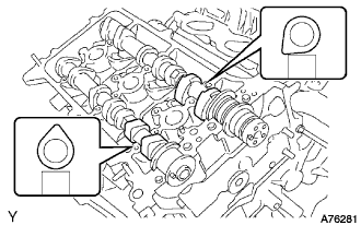
Place the 2 camshafts onto the cylinder head with the cam lobes of No. 1 cylinder facing each direction as shown in the illustration.
![]() |
Install the 8 bearing caps in their proper locations.
Apply a light coat of engine oil to the threads and under the heads of the bearing cap bolts.
![]() |
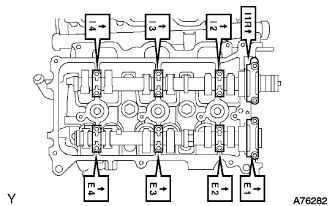
Using several steps, install and tighten the 16 bearing cap bolts uniformly in the sequence as shown in the illustration.
![]() |
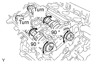
Turn the camshafts clockwise until the knock pin comes to 90° position to the cylinder head.
| 11. INSTALL NO. 2 CHAIN TENSIONER ASSEMBLY |
![]() |
While pushing in the tensioner, insert a pin of φ1.0 mm (0.039 in.) into the hole to fix it.
![]() |
Install the No. 2 chain tensioner with the bolt.
| 12. INSTALL CAMSHAFT TIMING GEARS AND NO. 2 CHAIN (for Bank 1) |
![]() |
Align the mark links (yellow) with the timing marks (1-dot mark) of the camshaft timing gears as shown in the illustration.
![]() |
Align the timing marks on the camshaft timing gears with the timing marks on the bearing caps, and install the camshaft timing gears with the chain to the RH camshafts.
Temporarily install the 2 camshaft timing gear bolts.
![]() |
Hold the hexagonal portion of the camshaft with a wrench, and tighten the 2 bolts.
Remove the pin from the No. 2 tensioner.
| 13. INSTALL WATER BY-PASS JOINT RR |
![]() |
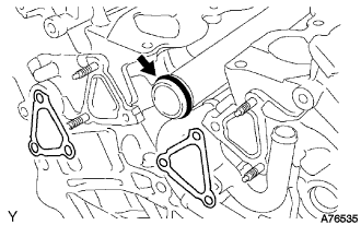
Install a new O-ring to the water outlet pipe.
Apply soapy water to the O-ring.
Install 2 new gaskets and water by-pass joint RR with the 2 bolts and 4 nuts.
Connect the heater hose.
Connect the engine coolant temperature sensor connector.
| 14. INSTALL INTAKE MANIFOLD |
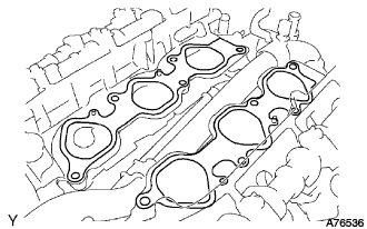
![]() |
Set a new gasket on each cylinder head.
Set the intake manifold on the cylinder heads.
Install and tighten the 10 bolts uniformly in several steps.
Connect the 6 fuel injector connectors.
| 15. CONNECT NO. 2 FUEL PIPE SUB-ASSEMBLY |
Push the tube connector into the pipe until the tube connector makes a "click" sound.
Install the fuel pipe clamp.
| 16. CONNECT NO. 1 FUEL PIPE SUB-ASSEMBLY |
Push the tube connector into the pipe until the tube connector makes a "click" sound.
Install the fuel pipe clamp.
| 17. INSTALL EXHAUST MANIFOLD SUB-ASSEMBLY LH |
![]() |
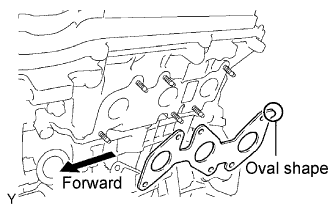
Set a new gasket to the LH cylinder head with the oval shape facing backward.
Install the exhaust manifold with the 6 nuts. Tighten the nuts uniformly in several steps.
Connect the A/F sensor connector.
| 18. INSTALL NO. 2 MANIFOLD STAY |
Install the No. 2 manifold stay with the 3 bolts.
| 19. INSTALL NO. 2 EXHAUST FRONT PIPE ASSEMBLY |
Install 2 new gaskets and the front pipe to the exhaust manifold.
Install the exhaust pipe front with the 2 bolts and 2 nuts.
| 20. INSTALL EXHAUST MANIFOLD SUB-ASSEMBLY RH |
![]() |
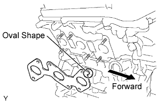
Set a new gasket to the RH cylinder head with the oval shape facing forward.
Install the exhaust manifold with the 6 nuts. Tighten the nuts uniformly in several steps.
Connect the A/F sensor connector.
| 21. INSTALL MANIFOLD STAY |
Install the manifold stay with the 3 bolts.
| 22. INSTALL EXHAUST PIPE ASSEMBLY FRONT |
Install a new gasket and the front pipe to the exhaust manifold.
Install the exhaust pipe front with 2 nuts.
| 23. INSTALL TRANSMISSION OIL FILLER TUBE SUB-ASSEMBLY |
Coat a new O-ring with ATF, and install it to the oil filler tube.
Push in the oil filler tube end into the oil pan lower tube.
Install the oil filler tube with the bolt.
Install the ATF level gauge.
| 24. INSTALL NO. 1 COOL AIR INLET |
Install the cool air inlet with air cleaner hose with the 2 bolts.
| 25. INSTALL CHAIN SUB-ASSEMBLY |
| 26. ADD ENGINE OIL |
Fill with fresh engine oil.
| Drain and refill with oil filter change | 5.2 liters (5.5 US qts, 4.6 lmp. qts) |
| Drain and refill without oil filter change | 4.9 liters (5.2 US qts, 4.3 lmp. qts) |
| Dry fill | 6.0 liters (6.3 US qts, 5.3lmp. qts) |
Reinstall the oil filler cap.
| 27. ADD ENGINE COOLANT |
| 28. CHECK FOR ENGINE OIL LEAKAGE |
| 29. CHECK FOR ENGINE COOLANT LEAKAGE |
Fill the radiator with coolant and attach a radiator cap tester.
Pump it to 118 kPa (1.2 kgf/cm2 17.1 psi), then check for leakage.
| 30. CHECK FOR FUEL LEAKAGE |
| 31. CHECK FOR EXHAUST GAS LEAKAGE |
| 32. INSPECT ENGINE IDLE SPEED |
Warm up the engine.
![]() |
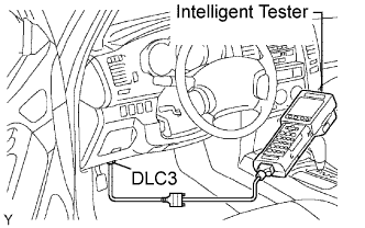
When using the intelligent tester:
Connect the intelligent tester to the DLC3.
Select the following menu items: DIAGNOSIS / ENHANCED OBD ll / DATA LIST / ENGINE SPD.
Inspect the engine idling speed.
![]() |
When not using the intelligent tester:
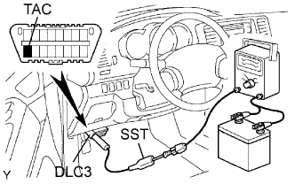
Using SST, connect the terminal 8 (TAC) of the DLC3.
Race the engine speed at 2,500 rpm for approximately 90 seconds.
Inspect the engine idling speed.
| 33. INSPECT COMPRESSION |
Warm up and stop the engine.
Remove the V-bank cover.
Remove the air cleaner assembly.
Remove the intake air surge tank .
Remove the 6 ignition coils.
Remove the 6 spark plugs.
Disconnect the 6 injector connectors.
![]() |
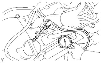
Inspect the cylinder compression pressure.
Insert a compression gage into the spark plug hole (Procedure "A").
Fully open the throttle (Procedure "B").
While cranking the engine, measure the compression pressure (Procedure "C").
Repeat procedures "A" through "C" for each cylinder.
If the cylinder compression is low, pour a small amount of engine oil into the cylinder through the spark plug hole and repeat procedures "A" through "C" for cylinders with low compression.
Connect the 6 injector connectors.
Install the 6 spark plugs.
Install the 6 ignition coils.
Install the intake air surge tank .
Install the air cleaner assembly.
Install the V-bank cover.
| 34. INSPECT CO/HC |
Start the engine.
Run the engine at 2,500 rpm for approximately 180 seconds.
![]() |
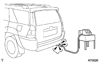
Insert the CO/HC meter testing probe at least 40 cm (1.3 ft) into the tailpipe during idling.
Immediately check the CO/HC concentration during idling and/or at 2,500 rpm.
If the CO/HC concentration does not comply with regulations, troubleshoot in the order given below.
Check the A/F sensor and heated oxygen sensor operation.
See the table below for possible causes, then inspect and correct the applicable causes if necessary.
| CO | HC | Symptom | Causes |
| Normal | High | Rough idling |
|
| Low | High | Rough idling (Fluctuating HC reading) |
|
| High | High | Rough idling (Black smoke from exhaust) |
|