FOUR WHEEL DRIVE CONTROL SYSTEM > DETAILS


FUNCTION OF MAIN COMPONENTS
*: Models with Multi-terrain select system

Component
Function
Combination Meter Assembly
4WD Indicator Light
Illuminates to inform the driver that the drive type is 4WD.
4LO Indicator Light
Illuminates to inform the driver that the transfer position is low range.
A/T P Warning Light
Illuminates to warn the driver that the transfer position is neutral range and parking rock does not function.
Accessory Meter*
Multi-information Display
Displays a message to guide the driver to switch transfer mode.
Transfer
Transfer Shift Lever
Shifts the transfer mode (H2, H4 or L4).
Transfer Neutral Switch
Detects the transfer neutral signal.
4WD Detection Switch
Detects the drive type is 4WD.
L4 Position Switch
Detects the transfer position is Low.
Front Differential
  1. A.D.D. Shift Actuator
    1. A.D.D. Shift Motor
    2. A.D.D. Motor Limit Switch
    3. A.D.D. Detection Switch
  1. Switches the drive type (2WD or 4WD)
  2. Detects the A.D.D. state (ON or OFF).
Four Wheel Drive Control ECU
Receives the switch signals and controls the A.D.D. shift actuator.
ECM
Outputs signals such as the shift position signal, throttle position signal, and crankshaft position signal to the four wheel drive control ECU.

CONSTRUCTION


  1. Transfer

    1. The VF2A transfer is a part-time 2-speed transfer case. In this transfer, a planetary gear unit is used as a reduction mechanism and a silent chain is used to quietly transfer power to the front output shaft.

    2. When shifting from H4 to L4, the transfer shift lever operates the high and low shift fork.


    3. A low viscosity oil is used, also improving fuel consumption.
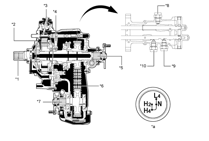

      V100368E01


      Text in Illustration 
      *1
      Transfer Input Shaft
      *2
      Planetary Gear Unit
      *3
      Transfer Shift Lever
      *4
      High and Low Shift Fork
      *5
      Rear Output Shaft
      *6
      Silent Chain
      *7
      Front Output Shaft
      *8
      4WD Detection Switch
      *9
      Transfer Neutral Switch
      *10
      L4 Position Switch
      *a
      Transfer Shift Pattern
      -
      -


  2. Planetary Gear Unit

    1. The planetary gear unit consists of the planetary sun gear, 4 planetary pinion gears, and planetary carrier.

    2. The planetary sun gear is integrated with the transfer input shaft.

    3. 4 planetary pinion gears are fitted to the planetary carrier. Each pinion gear shaft is fixed to the planetary carrier. A planetary spline piece is fitted to the rear of the planetary carrier. When the planetary carrier is to be connected to the output shaft, the power is transferred after engaging the splines on the spline piece with the splines on the high and low clutch sleeve. The high and low clutch sleeve is installed rearward of the transfer input shaft on the high and low clutch hub that is splined to the output shaft.


    4. The planetary ring gear is fixed to the transfer case and its internal teeth mesh with the planetary pinion gears.
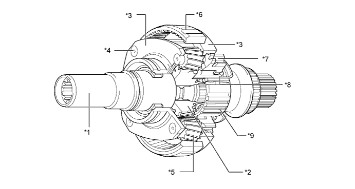

      V100369E02


      Text in Illustration 
      *1
      Transfer Input Shaft
      *2
      Planetary Sun Gear
      *3
      Planetary Carrier
      *4
      Pinion Shaft
      *5
      Planetary Pinion Gear
      *6
      Planetary Ring Gear
      *7
      Planetary Spline Piece
      *8
      High And Low Clutch Sleeve
      *9
      High And Low Clutch Hub
      -
      -


  3. Automatic Disconnection Differential (A.D.D.) Shift Actuator


    1. The A.D.D. shift actuator contains the A.D.D. shift motor, A.D.D. motor limit switch and A.D.D. detection switch. It should not be disassembled.
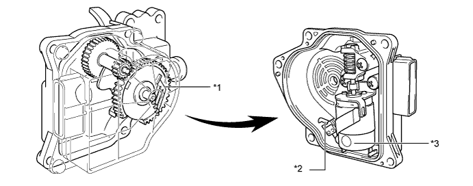

      V100370E01


      Text in Illustration 
      *1
      A.D.D. Motor Limit Switch (DL1, DL2)
      *2
      A.D.D. Detection Switch
      *3
      A.D.D. Shift Motor
      -
      -


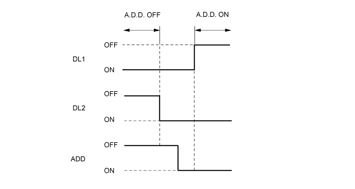
    2. The A.D.D. motor limit switch has two contact point switches (DL1, DL2). Different combinations of the two contact point switches and A.D.D. detection switch (ADD) allow detection of the A.D.D. state (ON or OFF).
      V100371E01


OPERATION


  1. Planetary Gear Unit Operation


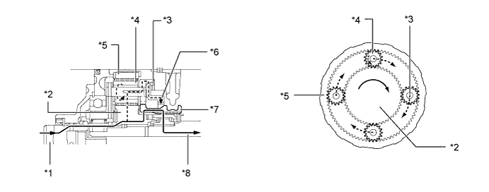
    1. In the H2/H4 position, the input shaft is directly connected to the output shaft via the splines at the rear of the transfer input shaft which make this connection via the movable high and low clutch sleeve.
      The high and low clutch sleeve is constantly meshed with the rear output shaft via the high and low clutch hub. Thus, the rotation of the input shaft is transmitted to the high and low clutch sleeve, to the high and low clutch hub, then to the rear output shaft.


      V100373E01


      Text in Illustration 
      *1
      Transfer Input Shaft
      *2
      Planetary Sun Gear
      *3
      Planetary Carrier (Pinion Shaft)
      *4
      Planetary Pinion Gear
      *5
      Planetary Ring Gear
      *6
      Planetary Spline Piece
      *7
      High And Low Clutch Sleeve
      *8
      Rear Output Shaft


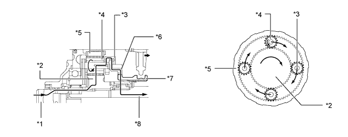
    2. In the L4 position, the external teeth of the high and low clutch sleeve are meshed with the planetary carrier via the spline piece. Thus, the rotation of the input shaft is transmitted from the planetary sun gear, to the planetary pinion gears, to the planetary pinion gear shafts, to the planetary carrier, to the planetary spline piece, to the high and low clutch sleeve, through the high and low clutch hub, to the rear output shaft.


      V100372E01


      Text in Illustration 
      *1
      Transfer Input Shaft
      *2
      Planetary Sun Gear
      *3
      Planetary Carrier (Pinion Shaft)
      *4
      Planetary Pinion Gear
      *5
      Planetary Ring Gear
      *6
      Planetary Spline Piece
      *7
      High And Low Clutch Sleeve
      *8
      Rear Output Shaft


  2. Automatic Disconnection Differential (A.D.D.) Shift Actuator Operation


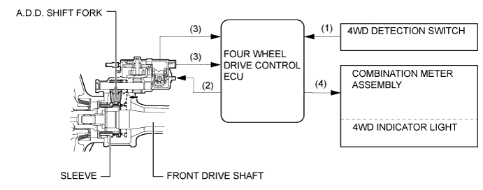
    1. From 2WD (H2) to 4WD (H4)


      V100374E03


      Step
      System Operation
      (1)
      When the transfer shift lever is shifted from H2 to H4, the 4WD detection switch ON signal is input into the four wheel drive control ECU.
      (2)
      The four wheel drive control ECU actuates the A.D.D. shift motor.
      (3)
      The operation of the A.D.D. shift motor causes the A.D.D. shift fork and sleeve to move toward the left side, thus connecting the front differential and front drive shafts. As result, the torque from the transfer is transmitted to the front wheels.
      (4)
      The four wheel drive control ECU turns on the 4WD indicator light.


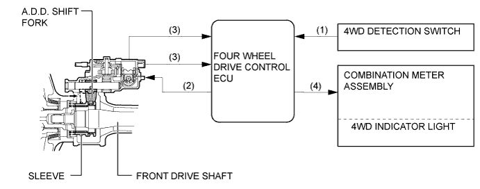
    2. From 4WD (H4) to 2WD (H2)


      V100375E03


      Step
      System Operation
      (1)
      When the transfer shift lever is shifted from H4 to H2, the 4WD detection switch OFF signal is input into the four wheel drive control ECU.
      (2)
      The four wheel drive control ECU actuates the A.D.D. shift motor.
      (3)
      The operation of the A.D.D. shift motor causes the A.D.D. shift fork and sleeve to move toward the right side, thus disconnecting the front differential and front drive shafts. As result, the torque from the transfer is not transmitted to the front wheels.
      (4)
      The four wheel drive control ECU turns off the 4WD indicator light.