Rear Differential Lock System
The table below shows how the four wheel drive control ECU (rear differential lock) controls the rear differential lock actuator and rear differential lock indicator light based on the computer signals received from the switches and signals depending on the operation of the rear differential lock switch.
*: When the vehicle speed is higher than 8 km/h (5 mph), the computer prohibits shifting into the "LOCK" mode, and blinks the rear differential lock indicator light.Operation Conditions for 2WD Models Switches and Signal Condition Rear Differential Condition Indicator Light Lock Switch Vehicle Speed Lock Detection Switch OFF - OFF Free Turn off ON 8 km/h (5 mph) or higher Blinks 1* 8 km/h (5 mph) or lower Lock actuator is operating Blinks 2 ON Lock Turn on
*: When the vehicle speed is higher than 8 km/h (5 mph), the computer prohibits shifting into the "LOCK" mode, and blinks the rear differential lock indicator light.Operation Condition for 4WD Models Switches and Signal Condition Rear Differential Condition Indicator Light Lock Switch L4 Position Switch Vehicle Speed Lock Detection Switch OFF OFF - OFF Free Turn off ON Blinks 1 ON 8 km/h (5 mph) or higher Blinks 1* 8 km/h (5 mph) or lower Lock actuator is operating Blinks 2 ON Lock Turn on Rear Differential Lock Indicator Light Blinking Pattern
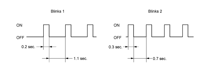
- HINT:
- When the rear differential lock is operating, the skid control ECU stops the operation of brake control functions (ABS, Brake Assist, TRAC/A TRAC and VSC) and turns on the ABS warning light.