POWER STEERING SYSTEM > DETAILS


FUNCTION OF MAIN COMPONENTS

Component
Function
Rack and Pinion Power Steering Gear Assembly
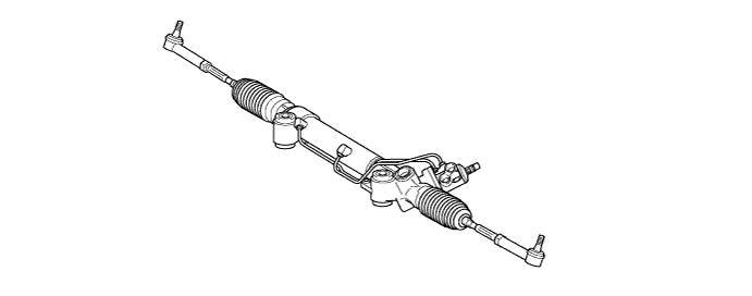
Increases operation force of the steering wheel and transmits operation force to the front wheel.
Vane Pump Assembly
Drives in accordance with the engine to pump power steering fluid to the steering gear assembly.
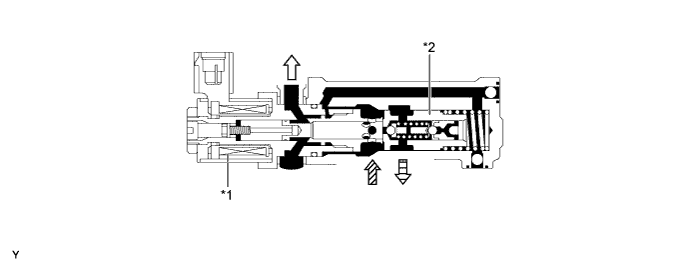
VFC Solenoid Valve
(Built into Vane Pump)
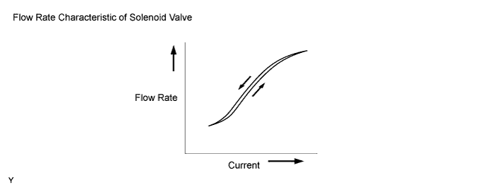
Controls the discharge flow rate and is controlled by the power steering ECU.
Vane Pump Oil Reservoir Assembly
Stores the power steering fluid.
Combination Meter Assembly
- Power Steering Warning Light
Lights up to alert the driver that the power steering ECU has detected a malfunction in the power steering system.
Steering Angle Sensor
Detects the steering direction and angle of the steering wheel.
Power Steering ECU Assembly
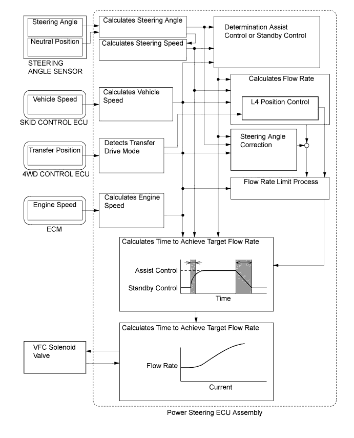
Calculates the optimum discharge flow rate in accordance with the vehicle condition, and controls the VFC solenoid valve.
Skid Control ECU
Sends the vehicle speed signal.
ECM
Sends the engine speed signal.

SYSTEM CONTROL


  1. The power steering ECU effects the following controls:

    Control
    Function
    Flow Rate Control
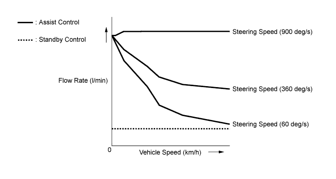
    1. The flow rate control effects control in accordance with the vehicle speed, steering angle, and steering speed conditions. It effects assist control when the steering wheel is being operated and standby control when the steering wheel is not being operated. Thus, it prevents the vane pump from discharging excessive flow, which lightens the load on the engine and improves fuel economy. Also, the steering angle correction is made to determine an optimal discharge flow rate.
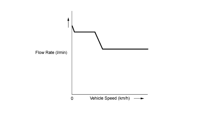
    2. The flow rate control allows the discharge flow rate to change as little as possible in accordance with steering speed and vehicle speed when in L4 position.
    Steering Angle Correction
    Determines the discharge flow rate in accordance with driving conditions, such as steering at standstill, cornering, and straightline driving.


    X102334E02


  2. Standby Control or Assist Control

    1. The standby control or assist control is performed in accordance with vehicle condition such as vehicle speed, steering angle, and steering speed.

      Control
      Standby Control
      Assist Control
      Vehicle Condition
      Vehicle speed 0 km/h (0 mph)
      Steering Speed Equal 0 deg/s
      (For 10 seconds or more)
      Steering Speed Greater than 0 deg/s
      Vehicle speed more than 0 km/h (0 mph)
      Steering Angle Less than 4.5°
      (For 10 seconds or more)
      Steering Angle Greater than or Equal to 4.5°

    2. The assist flow rate is determined in accordance with the vehicle speed and steering speed.


    3. For 3 seconds after the engine switch is turned on (IG), the flow rate is controlled at 10.5 l/min. After that, the flow rate is controlled as shown in the graph below:

      X102332E01


    4. In off-road driving, the steering force amount is important information for understanding the condition of the contact between the tire and the road. Accordingly, this system has the control feature of allowing the discharge flow rate to change as little as possible in accordance with the vehicle speed and steering speed when in transfer drive mode L4.

      X101416E01


  3. Steering Angle Correction

    1. Based on the steering angle and vehicle speed signals, this function corrects the flow rate in accordance with the driving conditions. Thus, it ensures an optimal steering feeling for every steering condition, such as steering at standstill, cornering, and straightline driving.

    2. The correction flow rate is 0 l/min while the steering is operated with the vehicle at standstill or driving straight (steering angle is +/- 0° or less).


    3. The correction flow rate decreases when the vehicle speed and steering angle increase.
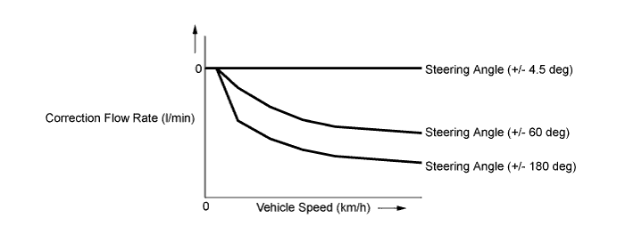

      X102333E01


CONSTRUCTION


  1. Rack and Pinion Power Steering Gear Assembly

    1. Operability has been improved through a lightweight, compact rack and pinion type steering gear assembly.


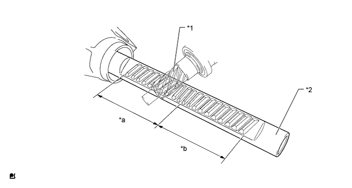
    2. A variable gear ratio type steering rack is used. This steering rack changes the gear ratio gradually by changing the gear teeth form. The gear ratio is set larger around the steering center and smaller around the end position. Thus, rack stroke around the end position is larger to reduce the steering operation while ensuring the moderate response around the steering center.


      X102419


      X102420E02


      Text in Illustration 
      *1
      Pinion Gear
      *2
      Rack
      *a
      Steering Center Position
      *b
      Steering End Position


  2. Vane Pump Assembly

    1. A compact and lightweight vane pump is used.


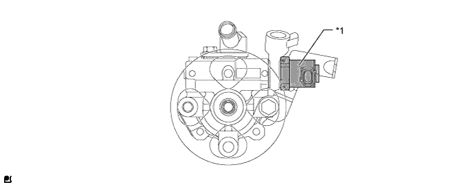
    2. A VFC solenoid valve is provided to control the discharge flow rate.


      X106836E01


      Text in Illustration 
      *1
      VFC Solenoid Valve
      -
      -

      X102422E01


      Text in Illustration 
      *1
      VFC Solenoid Valve
      *2
      Flow Control Valve
      V100136
      To Rack and Pinion Power Steering Gear
      V100137
      From Vane Pump
      V100138
      To Vane Pump
      -
      -

      X101420E01


FAIL-SAFE
  1. If the power steering ECU detects a malfunction in this system, it illuminates the power steering warning light to alert the driver of the malfunction.

  2. If a malfunction occurs in any of the sensors, the power steering ECU prevents standby control and performs the following fail-safe control.

    Fail-safe Control List 
    Malfunction
    Fail-safe Control
    Steering Angle Signal
    1. Fixes the steering angle to 0°
    2. Fixes the steering speed to 360 deg/sec
    3. Steering angle correction is canceled
    Steering Zero Point memory
    1. Fixes the steering angle to 0°
    2. Steering angle correction is canceled
    Vehicle Speed Signal
    1. Fixes the vehicle speed to 40 km/h (24.9 mph)
    Steering Angle Signal and Steering Zero Point Memory
    1. Fixes the steering angle to 0°
    2. Fixes the steering speed to 360 deg/sec
    3. Steering angle correction is canceled
    Steering Angle Signal and Vehicle Speed Signal
    1. Fixes the steering angle to 0°
    2. Fixes the steering speed to 360 deg/sec
    3. Fixes the vehicle speed to 40 km/h (24.9 mph)
    4. Fixes the discharge flow rate to 8.5 l/min.
    Steering Zero Point Memory and Vehicle Speed Signal
    1. Fixes the steering angle to 0°
    2. Fixes the vehicle speed to 40 km/h (24.9 mph)
    3. Steering angle correction is canceled
    Steering Angle Signal, Steering Zero point Memory and Vehicle Speed Signal
    1. Fixes the steering angle to 0°
    2. Fixes the steering speed to 360 deg/sec
    3. Fixes the vehicle speed to 40 km/h (24.9 mph)
    4. Fixes the discharge flow rate to 8.5 l/min.


DIAGNOSIS
  1. If the power steering ECU detects a malfunction in the VFC power steering system, the power steering warning light will illuminate to inform the driver.

  2. At the same time, the Diagnostic Trouble Code (DTC) is stored in the memory. The DTC stored in the power steering ECU are output to the Techstream connected to the DLC3. For details, refer to the Repair Manual.