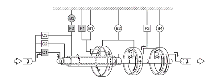
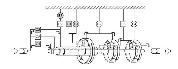
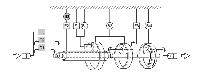
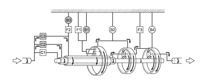
AUTOMATIC TRANSMISSION SYSTEM > DETAILS


SYSTEM CONTROL
  1. The electronic control system of the A750F automatic transmission consists of the control functions listed below:

    System
    Function
    Clutch Pressure Control
    1. Controls the pressure that is applied directly to B2 brake and C3 clutch by actuating the linear solenoid valves SL1 and SL2 in accordance with the ECM signals.
    2. The solenoid valve SLT and SL1 minutely control the clutch pressure in accordance with the engine output and driving conditions.
    Line Pressure Control
    Based on the throttle opening angle and various signals, the ECM sends a signal to solenoid valve SLT to generate line pressure that varies according to the engine output and to allow smooth gear changes.
    Lock-up Timing Control
    The ECM sends current to the solenoid valve SLU based on signals from various sensors and engages or disengages the lock-up clutch.
    Flex Lock-up Clutch Control
    1. Controls the solenoid valve SLU, provides an intermediate mode between the ON/OFF operation of the lock-up clutch, and increases the operating range of the lock-up clutch to improve fuel economy.
    2. The flex lock-up clutch control operates in 3rd, 4th and 5th gears in both D and S5 range, 3rd and 4th gears in the S4 range and 3rd gears in the S3 range.
    Artificial Intelligence Shift Control
    (AI-shift Control)
    Based on the signals from various sensors, the ECM determines the road condition and the intention of the driver. While the pattern select switch is in POWER, the shift pattern is biased toward sporty driving. Thus, an appropriate shift pattern is automatically determined to improve drivability.
    Multi-mode Automatic Transmission
    The ECM appropriately controls the automatic transmission in accordance with the range position selected while the shift lever is in S.
    Fail-safe
    If a malfunction is detected in the sensors or solenoids, the ECM performs fail-safe control to prevent the vehicle's drivability from being affected significantly.
    Diagnosis
    When the ECM detects a malfunction, the ECM makes a diagnosis and memorizes the information that relates to the fault.


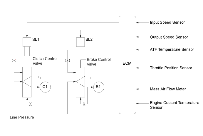
  2. Clutch to Clutch Pressure Control

    1. This control is adopted for shifting from 4th to 5th gear and from 5th to 4th gear.


    2. Solenoid valves SL1 and SL2 are actuated in accordance with the signals from the ECM, and guides this output pressure directly to the control valves B1 and C1 in order to regulate the line pressure that acts on the B1 brake and C1 clutches. As a result, responsive and excellent shift characteristics are realized.

      X101965E02


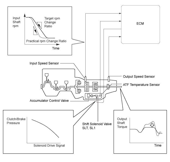
  3. Clutch Pressure Optimal Control


    1. The ECM monitors the signals from various sensors, such as the speed sensor NT, allowing shift solenoid valves SLT and SL1 to minutely control the clutch pressure in accordance with engine output and driving conditions. As a result, smooth shift characteristics have been realized.

      X101966E02


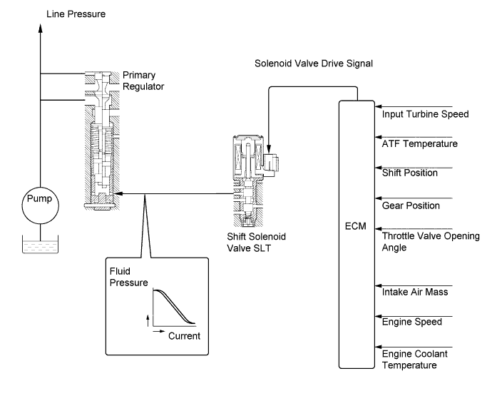
  4. Line Pressure Optimal Control

    1. Through the use of the solenoid valve SLT, the line pressure is optimally controlled in accordance with the engine torque information, as well as with the internal operating conditions of the torque converter and the transmission.


    2. Accordingly, the line pressure can be controlled minutely in accordance with the engine output, traveling condition, and the ATF temperature, thus realizing smooth shift characteristics and optimizing the workload of the oil pump (reducing unnecessary parasitic losses).

      X101607E04


  5. Flex Lock-up Clutch Control

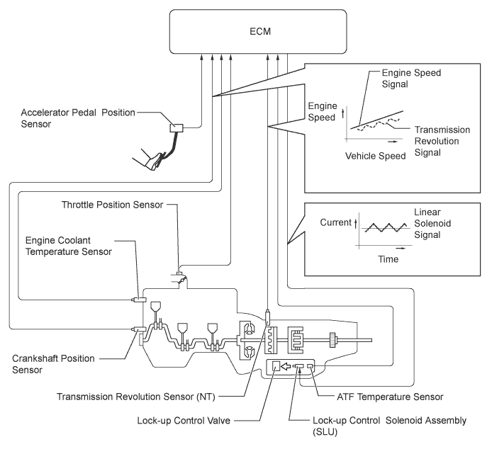
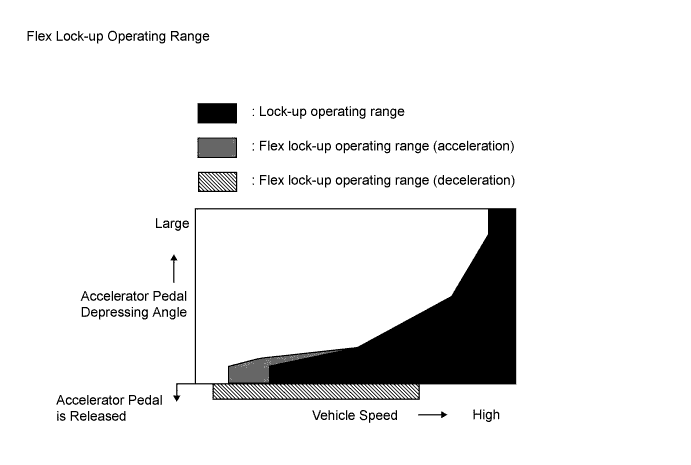
    1. In the low-to-mid-speed range, this flex lock-up clutch control regulates the shift solenoid valve SLU to provide an intermediate mode between the on and off operations of the lock-up clutch in order to improve the energy transmitting efficiency. As a result, the operating range of the lock-up clutch has been increased and fuel economy has been improved. The flex lock-up clutch control operates in 3rd, 4th and 5th gears when the shift lever is in D or in the S5 range, and in 4th gear when the shift lever is in the S4 range.


    2. Even when the vehicle is decelerating (the accelerator pedal is released), the flex lock-up clutch control operates. Therefore, the fuel-cut area of the engine has been expanded and fuel economy has been improved.
      X101959E05


      X102147E05


      Flex Lock-up Clutch Control Operation 
      Gear
      Shift Lever Position or Shift Range
      D, S5
      S4
      1st
      X
      X
      2nd
      X
      X
      3rd
      ○*1
      X
      4th
      ○
      ○*2
      5th
      ○
      -
      ○: Operates
      X: Does not operate
      -: Not applicable
      *1: Flex lock-up clutch control operates during acceleration.
      *2: Flex lock-up clutch control operates during deceleration.


  6. Artificial Intelligence Shift Control (AI-shift Control)

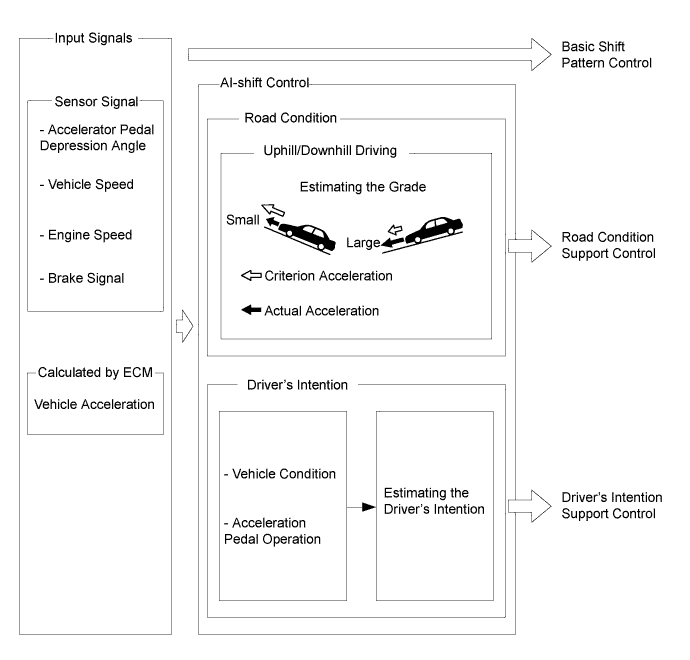
    1. The automatic transaxle gear is determined by the shift pattern, which uses the vehicle speed and accelerator pedal depressing angle.

    2. Additionally, AI-shift control enables the ECM to estimate the road conditions and the driver's intention in order to automatically control the shift pattern in the optimal manner. As a result, a comfortable ride has been achieved.

    3. The AI-shift control includes road condition support control and driver's intention support control.


    4. The AI-shift control determines optimal transaxle control based on input signals and automatically changes the shift pattern.

      X101610E04


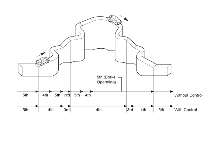
    5. Under road condition support control, ECM determines the throttle opening angle and the vehicle speed whether the vehicle is being driven uphill or downhill. To achieve the optimal drive force while driving uphill, this control prevents unnecessary upshifts. To achieve the optimal engine brake effect while driving downhill, this control automatically performs downshifts.

      X101969E01


  7. Multi-mode Automatic Transmission

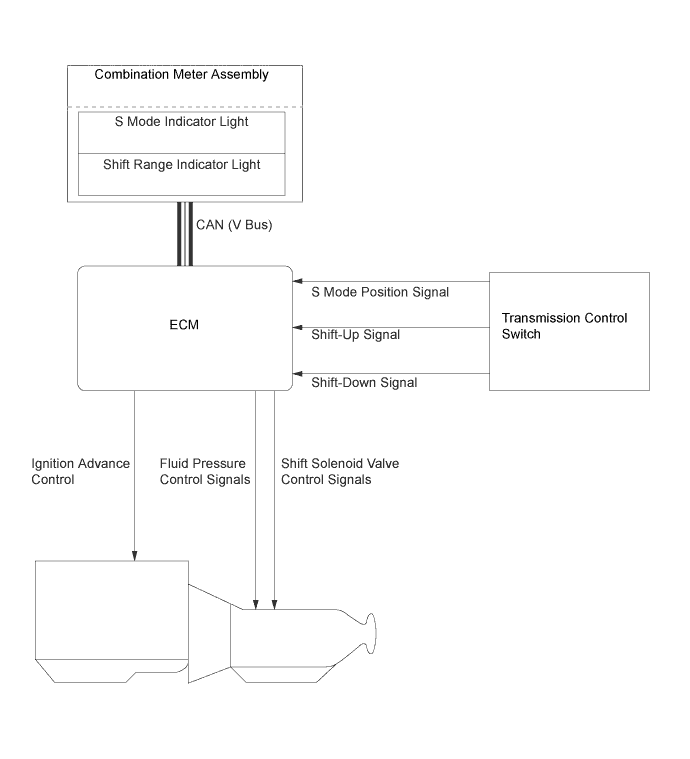
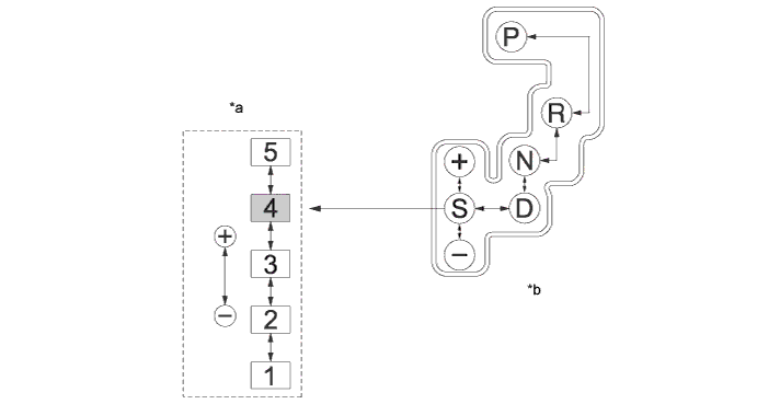
    1. The driver can select the desired shift range by moving the shift lever to "+" (forwards) or to "-" (backwards) while in S.

    2. The multi-mode automatic transmission is designed to allow the driver to switch the gear ranges.


    3. An S mode indicator which illuminates when the shift lever is in S and a shift range indicator which indicates the shift range have been provided in the combination meter.

      X101970E02

    4. The driver selects the S mode position by engaging the shift lever. At this time, the shift range position selects the 4th or 5th range according to the vehicle speed. (During AI-shift control, the shift range that has the currently controlled gear position as the maximum usable gear position will be displayed.) Then, the shift range positions change one at a time, as the driver moves the shift lever to the front ("+" position) or to the rear ("-" position).

    5. Under this control, the ECM effects optimal shift control within the usable gear range that the driver has selected. As with an ordinary automatic transmission, it shifts to the 1st gear when the vehicle is stopped.


    6. When the shift lever is in S, the S mode indicator light in the combination meter illuminates. The shift range indicator light indicates the state of the shift range position that the driver has selected.

      X101971E01


      Text in Illustration 
      *a
      Transition of Shift Ranges
      *b
      Shift Pattern
      V100145
      Default Shift Range
      -
      -

      Usable Gear Chart 
      Shift Range
      Shift Range Indicator Indication
      Usable Gear
      S5
      5
      5th ←→ 4th ←→ 3rd ←→ 2nd ←→ 1st
      S4
      4
      4th ←→ 3rd ←→ 2nd ←→ 1st
      S3
      3
      3rd ←→ 2nd ←→ 1st
      S2
      2
      2nd ←→ 1st
      S1
      1
      1st

FUNCTION


  1. Shift Lock System

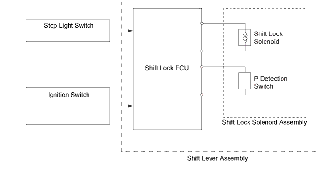
    1. The shift lock mechanism prevents the shift lever from being moved to a position other than P, unless the ignition switch is on (IG), and the brake pedal is pressed. This mechanism helps to prevent unintended acceleration.

    2. The shift lock system mainly consists of the shift lock ECU and shift lock override button.

    3. Shift lock ECU has a built-in P detection switch, and shift lock solenoid.

    4. The shift lock ECU uses the P detection switch to detect the shift lever position, and receives inputs from the stop light switch and the power source control ECU. Upon receiving these signals, the shift lock ECU turns on the shift lock solenoid in order to release the shift lock.


    5. A shift lock override button, which manually overrides the shift lock mechanism, is used.


      X101972E02


CONSTRUCTION


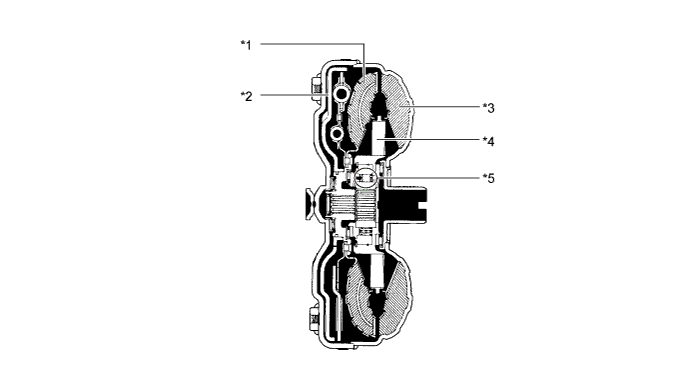
  1. Torque Converter


    1. A compact, lightweight and high-capacity torque converter is used. The torque converter supports flex lock-up clutch control, thus improving fuel economy.


      X101973E01


      Text in Illustration 
      *1
      Turbine Runner
      *2
      Lock-up Clutch
      *3
      Pump Impeller
      *4
      Stator
      *5
      One-way Clutch
      -
      -


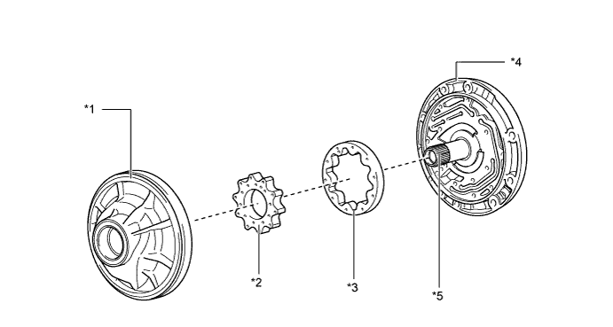
  2. Oil Pump

    1. The oil pump is operated by the torque converter. It lubricates the planetary gear units and supplies operating fluid pressure for hydraulic control.


    2. The material of the pump cover is aluminum to reduce weight.


      X101614E01


      Text in Illustration 
      *1
      Pump Body
      *2
      Drive Gear
      *3
      Driven Gear
      *4
      Pump Cover
      *5
      Stator Shaft
      -
      -


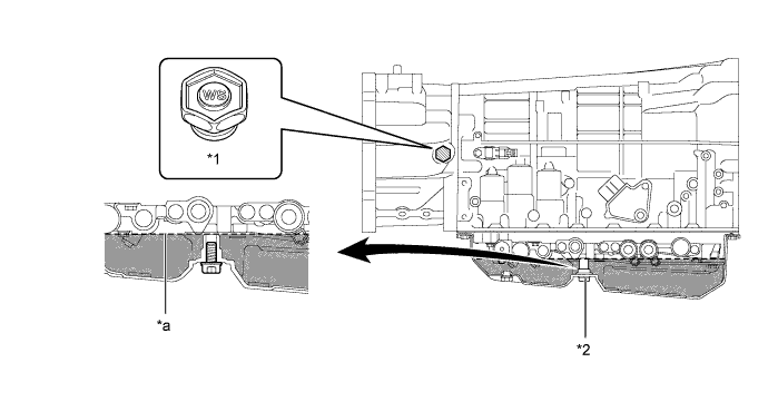
  3. ATF Filling Procedures

    1. The ATF filling procedure is changed in order to improve the accuracy of the ATF level when the transmission is being repaired or replaced. As a result, the oil filler tube and the oil level gauge used for a conventional automatic transmission are discontinued, eliminating the need to inspect the fluid level as a part of routine maintenance.


    2. This filling procedure uses a refill plug, overflow plug, ATF temperature sensor, and shift indicator light "D".


      X101999E01


      Text in Illustration 
      *1
      Refill Plug
      *2
      Overflow Plug
      *a
      Proper Level
      -
      -


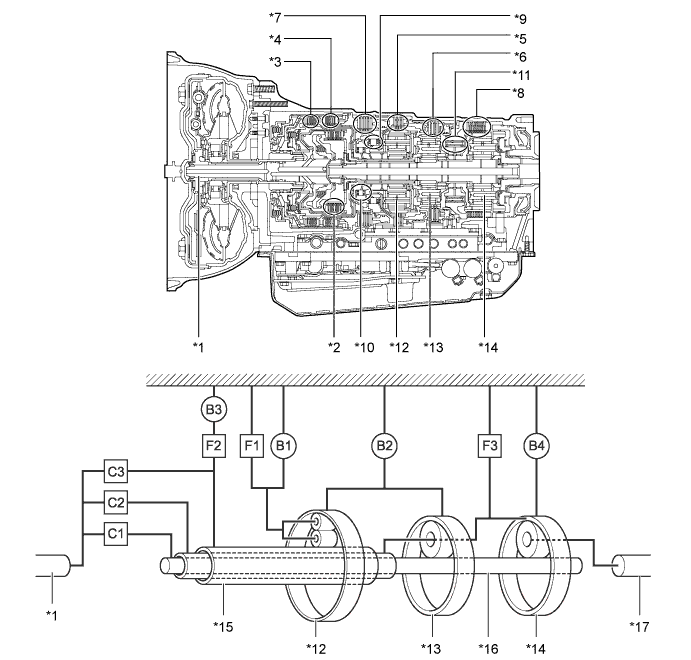
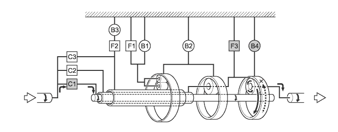
  4. Planetary Gear Unit


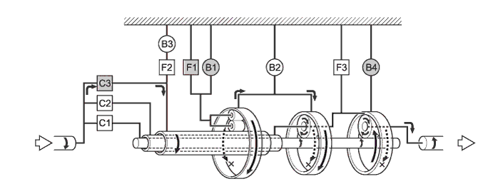
    1. The planetary gear unit consists of 3 planetary gear units, 3 clutches, 4 brakes, and 3 one-way clutches.


      X101975E01


      Text in Illustration 
      *1
      Input Shaft
      *2
      No.1 Clutch
      *3
      No. 2 Clutch
      *4
      No. 3 Clutch
      *5
      No. 1 Brake
      *6
      No. 2 Brake
      *7
      No. 3 Brake
      *8
      No. 4 Brake
      *9
      No. 1 One-way Clutch
      *10
      No. 2 One-way Clutch
      *11
      No. 3 One-way Clutch
      *12
      Front Planetary Gear
      *13
      Center Planetary Gear
      *14
      Rear Planetary Gear
      *15
      Sun Gear
      *16
      Intermediate Shaft
      *17
      Output Shaft
      *18
      -

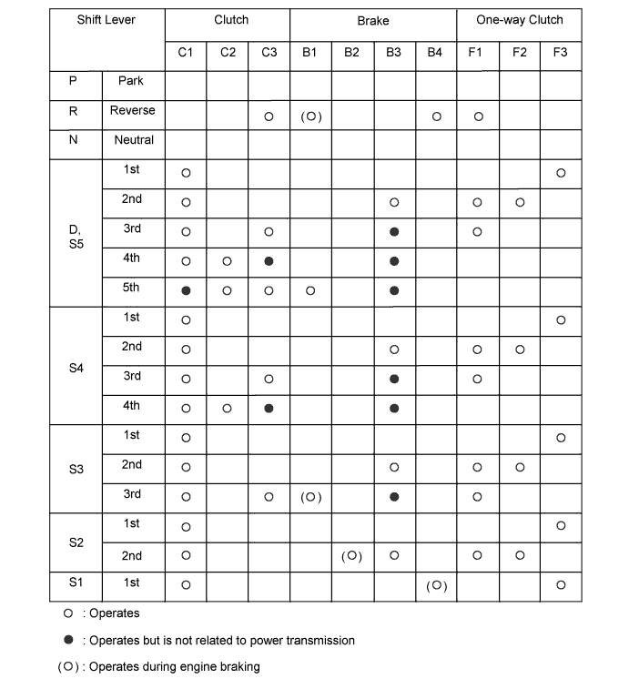
    2. The functions of the clutches and brakes are as follows:

      Component
      Function
      C1
      No. 1 Clutch
      Connects the input shaft and intermediate shaft.
      C2
      No. 2 Clutch
      Connects the input shaft and center planetary carrier.
      C3
      No. 3 Clutch
      Connects the input shaft and front sun gear.
      B1
      No. 1 Brake
      Prevents the front planetary carrier from turning either clockwise or counterclockwise.
      B2
      No. 2 Brake
      Prevents the front and the center ring gear from turning either clockwise or counterclockwise.
      B3
      No. 3 Brake
      Prevents outer race of F2 from turning both clockwise and counterclockwise.
      B4
      No. 4 Brake
      Prevents center planetary carrier and the rear ring gear from turning either clockwise or counterclockwise.
      F1
      No. 1 One-way Clutch
      Prevents the front planetary carrier from turning counterclockwise.
      F2
      No. 2 One-way Clutch
      When B3 is operating, the one-way clutch prevents the front sun gear from turning counterclockwise.
      F3
      No. 3 One-way Clutch
      Prevents the center planetary carrier and the rear ring gear from turning counterclockwise.
      Planetary Gears
      These gears change the route through which driving force is transmitted, in accordance with the operation of each clutch and brake, in order to increase or reduce the output shaft speed.


  5. Centrifugal Fluid Pressure Canceling Mechanism

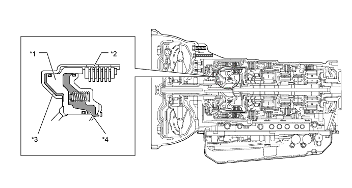
    1. The centrifugal fluid pressure canceling mechanism is used on clutches C1, C2 and C3.


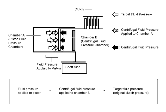
    2. Clutch shifting operation is affected not only by the valve body controlling fluid pressure but also by centrifugal fluid pressure that is present due to fluid in the clutch piston oil pressure chamber. The centrifugal fluid pressure canceling mechanism uses chamber B to reduce this effect applied to the chamber A. As a result, smooth shifting with excellent response has been achieved.


      X101976E01


      Text in Illustration 
      *1
      No.1 Clutch Piston
      *2
      No.1 Clutch
      *3
      Chamber A
      *4
      Chamber B


  6. Chamber B is filled by fluid supplied to the shaft for lubrication. As a result of filling chamber B, there is the same amount of fluid pressure due to centrifugal force on both sides of the piston. This cancels the effect of fluid pressure on the piston due to centrifugal force. Accordingly, it is not necessary to discharge the fluid through the use of a check ball, and highly responsive and smooth shifting characteristics are achieved.


    X101686E01


  7. Valve Body Unit


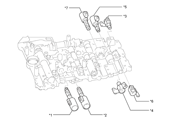
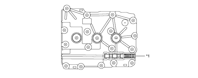
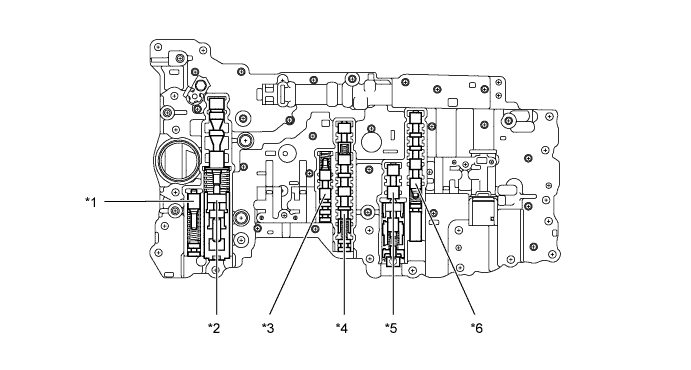
    1. The valve body consists of the upper (No. 1 and No. 2) and lower (No. 1 and No. 2) valve bodies and 7 solenoid valves.


      X101977E01


      Text in Illustration 
      *1
      Shift Solenoid Valve SLT
      *2
      Shift Solenoid Valve SL1
      *3
      Shift Solenoid Valve SR
      *4
      Shift Solenoid Valve S1
      *5
      Shift Solenoid Valve SLU
      *6
      Shift Solenoid Valve S2
      *7
      Shift Solenoid Valve SL2
      -
      -

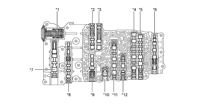
      X101978E01


      Text in Illustration (No. 1 Upper Valve Body:) 
      *1
      B1 Accumulator
      *2
      Clutch Lock Valve
      *3
      Solenoid Modulator Valve
      *4
      2 - 3 Shift Valve
      *5
      1 - 2 Shift Valve
      *6
      B1 Apply Control Valve
      *7
      Secondary Regulator Valve
      *8
      Lock-up Relay Valve
      *9
      Lock-up Control Valve
      *10
      C3 Check Valve
      *11
      3 - 4 Shift Valve
      *12
      Brake Control Valve

      X101979E01


      Text in Illustration (No. 2 Upper Valve Body:) 
      *1
      Coast Brake Relay Valve
      -
      -

      X101980E01


      Text in Illustration (Lower Valve Body:) 
      *1
      SLT Damper
      *2
      Primary Regulator Valve
      *3
      Clutch Control Valve
      *4
      Clutch Apply Control Valve
      *5
      Accumulator Control Valve
      *6
      Sequence Valve


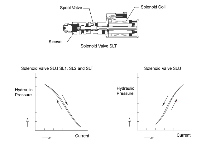
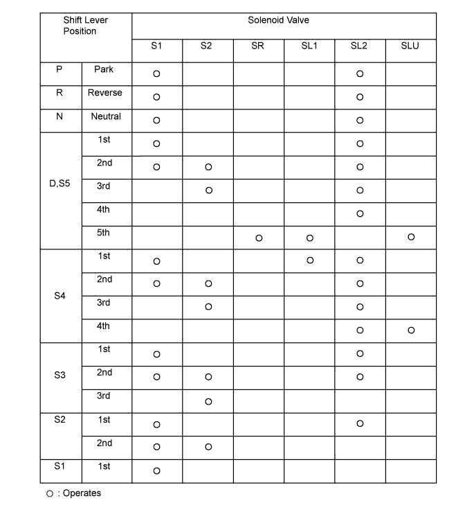
  8. Solenoid Valve SL1, SL2, SLT and SLU


    1. In order to provide hydraulic pressure in proportion to current that flows to the solenoid coil, the solenoid valve SL1, SL2, SLT, and SLU linearly controls the line pressure and clutch and brake engagement pressure based on the signals received from the ECM.


      X101981E03


      Solenoid Valve
      Function
      SL1
      1. Clutch pressure control.
      2. Accumulator back pressure control.
      SL2
      Brake pressure control.
      SLT
      1. Line pressure control.
      2. Accumulator back pressure control.
      SLU
      1. Lock-up clutch pressure control.


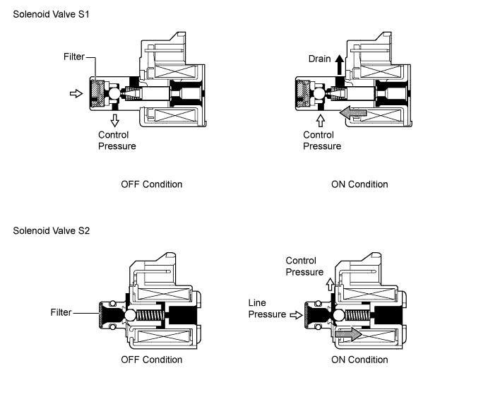
  9. Solenoid Valve S1, S2 and SR


    1. These solenoid valves are 3-way solenoid valves. A filter is provided at the tip of the solenoid valve to further improve operational reliability.


      X101982E04


      Solenoid Valve
      Type
      Function
      S1
      3-way
      1. Switches the 2-3 shift valve.
      S2
      3-way
      1. Switches the 1-2 shift valve.
      2. Switches the 3-4 shift valve.
      SR
      3-way
      1. Switches the clutch apply control valve.


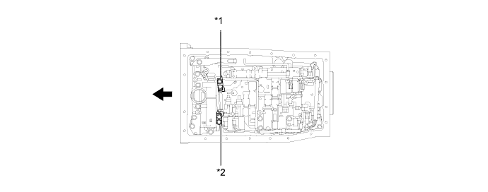
  10. ATF Temperature Sensor No.1 and No.2

    1. ATF temperature sensor No.1 (THO1) is used for hydraulic pressure control. This sensor is used for revision of the pressure that is used to apply clutches and brakes in the transmission. This helps to ensure smooth shift quality.


    2. ATF temperature sensor No.2 (THO2) is used as a basis for modifying the ECT shift timing control when the ATF temperature is high. It is also used for the ATF temp. warning light.


      X101983E04


      Text in Illustration 
      *1
      ATF Temperature Sensor No.1
      *2
      ATF Temperature Sensor No.2
      V100135
      Front
      -
      -


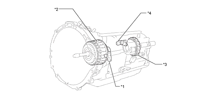
  11. Speed Sensors

    1. This automatic transmission uses a speed sensor NT and speed sensor SP2. Thus, the ECM can detect the timing of the shifting of the gears and appropriately control the engine torque and hydraulic pressure in response to the various conditions.

    2. These speed sensors are a pick-up coil type.

    3. The speed sensor NT detects the input speed of the transmission. The C3 clutch drum is used as the timing rotor for this sensor.


    4. The speed sensor SP2 detects the speed of the output shaft. The parking gear on the rear planetary gear is used as the timing rotor for this sensor.


      X101984E01


      Text in Illustration 
      *1
      Speed Sensor NT
      *2
      C3 Clutch Drum (Timing Rotor)
      *3
      Parking Gear (Timing Rotor)
      *4
      Speed Sensor SP2


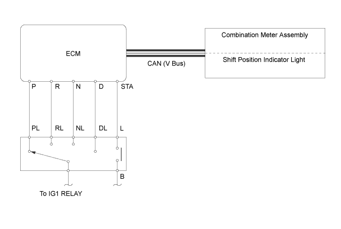
  12. Park/Neutral Position Switch


    1. The park/neutral position switch sends the P, R, N, D and STAR position signals to the ECM. It also sends signals for the shift position indicator light (P, R, N, and D).


      X101985E02


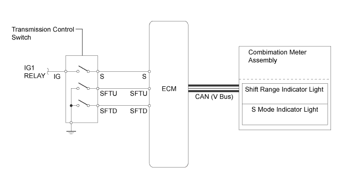
  13. Transmission Control Switch


    1. The transmission control switch detects whether the shift lever is in D or S, and detects the operating conditions of the shift lever (+ position or - position) if the S mode is selected, and sends signals to the ECM. At this time, the ECM turns on the shift range indicator light for the selected range.


      X101986E02


  14. Automatic Transmission Fluid (ATF) WS


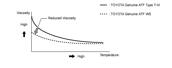
    1. TOYOTA genuine ATF WS is used to reduce the resistance of the ATF and improve the fuel economy by reducing its viscosity in the practical operating temperature range. At higher fluid temperatures, the viscosity is the same as that of TOYOTA genuine ATF Type T-IV, to ensure the durability of the automatic transmission.


      X100046E04


OPERATION


  1. Transmission Power Flow


    X101993E01


    X101994E01


    X101987E01


    Text in Illustration (1st Gear (D Position or S Mode):) 
    V100145
    Operates

    X101988E01


    Text in Illustration (2nd Gear (D Position or S Mode):) 
    V100145
    Operates

    X101989


    Text in Illustration (3rd Gear (D Position or S Mode):) 
    V100145
    Operates

    X101990


    Text in Illustration (4th Gear (D Position or S Mode):) 
    V100145
    Operates

    X101991


    Text in Illustration (5th Gear (D Position or S Mode):) 
    V100145
    Operates

    X101992


    Text in Illustration (Reverse Gear (R Position):) 
    V100145
    Operates


FAIL-SAFE
This function minimizes the loss of operability when an abnormality occurs in a sensor or solenoid. For details, refer to the Repair Manual.

DIAGNOSIS
  1. When the ECM detects a malfunction, the ECM records the malfunction and memorizes the information related to the fault. Furthermore, the ECM illuminates or blinks the Malfunction Indicator Lamp (MIL) in the combination meter assembly to inform the driver.

  2. The ECM will also store the Diagnostic Trouble Code (DTC) of the malfunctions. The DTCs stored in the ECM are output to the Techstream via the ECM and the DLC3.

  3. A permanent DTC is used for the DTCs associated with the illumination of the MIL. Permanent DTCs cannot be cleared by using the Techstream, disconnecting the battery terminal, or removing the EFI fuse.

  4. To clear other DTC that is stored in the ECM, use the Techstream, disconnect the cable from the battery terminal or remove the EFI fuse for 1 minute or longer.

  5. For details, refer to the Repair Manual.