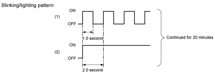
The side auto step system performs the following controls.
| Function | Outline |
| Automatic Deployment | When all of the following conditions have been satisfied, the RH (LH) side steps deploy automatically.
|
| Automatic Stowing | When all of the following conditions have been satisfied, the RH (LH) side steps stow automatically.
|
| Vehicle movement-induced stowing | When all of the following conditions have been satisfied, the steps stow automatically*1.
|
| Preventing Deployment | Preventing deployment of the step can be accomplished by switching the side auto step switch assembly from AUTO to OFF. |
| Jam Protection | If foreign objects or jams are detected during deployment (stowing), the motor is reversed, returning the step to its original position. |
- HINT:
- *1: After vehicle movement-induced stowing, the step will not return to its deployed position even when vehicle speed drops below 8 km/h when waiting for traffic signals, etc.
- *2: Additionally, when the side auto step controller ECU assembly detects a foreign object during vehicle movement-induced stowing, a reverse movement is induced once, deploying the step, and then the step is re-stowed if vehicle speed continues at 8 km/h or above. If the foreign object is not removed at this point, the step halts when it makes contact with the foreign object.
Jam Protection Function
If a foreign object is detected in a defined area when during the automatic deployment (stowing) operation, the side auto step controller ECU assembly reverses the motor and returns the step to its original position*1.
If the jam protection function activates three times in succession, the side auto step controller ECU assembly halts the step in the possession where the foreign object was detected*2.
- HINT:
- *1: To prevent erroneous activation, the side auto step controller ECU assembly does not detect foreign objects when the step is outside a defined area.
- *2: If the foreign object is removed before jam detection operates three times, normal functioning will resume after the automatic running board system operates once in response to door opening or closing.
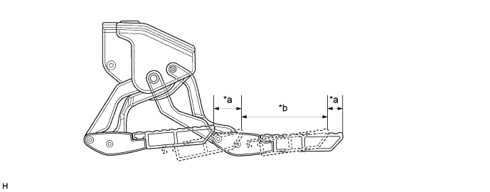
Text in Illustration *a Outside a Defined Area *b Defined Area The side auto step controller ECU assembly evaluates whether there is a jam based on changes in the width of the pulse signal from the hall IC inside the motor.
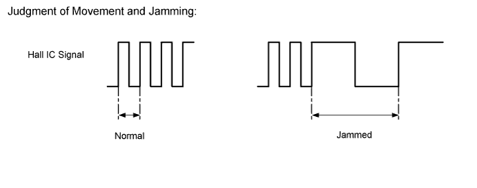
Fail-Safe Function
The side auto step controller ECU assembly will halt or prevent system operation if there is a fault in the circuit, hall IC, motor, link, or ECU.
If the fail-safe function activates, the indicator lamp in the combination meter assembly blinks, and if the step is not in its normal position, the indicator lamp lights, informing the user of abnormalities.