If the front wiper switch is turned to the INT position, current flows from capacitor C1, which is already charged, through terminals INT1 and INT2 of the front wiper switch to Tr1 (transistor). When Tr1 turns on, current flows from terminal +S of the front wiper switch to terminal +1 of the front wiper switch, then to terminal +1 of the wiper motor, then to the wiper motor and finally to ground, causing the wiper motor to operate. At the same time, current flows from capacitor C1 to terminal INT1 of the front wiper switch, and then to INT2. When the current flow from capacitor C1 ends, Tr1 turns off to turn off the relay contact point and halt the wiper motor.
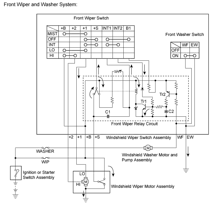
When the relay contact point turns off, capacitor C1 begins to charge again and Tr1 remains off until charging has been completed. This period corresponds to the intermittent time. When capacitor C1 is fully charged, Tr1 turns on and then the relay contact point turns on, causing the motor to operate again. This cycle is the intermittent operation.
The intermittent time can be adjusted by using the intermittent time adjust dial (variable resistor) to change the charge time of capacitor C1.