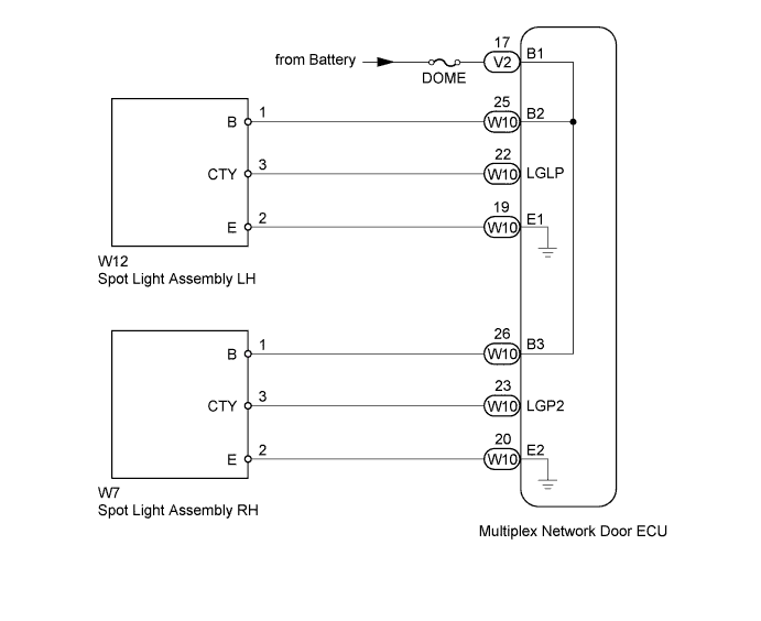
LIGHTING SYSTEM > Luggage Room Light Circuit |
| 1.PERFORM ACTIVE TEST USING TECHSTREAM (SPOT LIGHT) |
Using the Techstream, perform the Active Test (Click here).
| Tester Display | Test Part | Control Range | Diagnostic Note |
| Luggage Compartment Light | Spot light | ON/OFF | - |
|
| ||||
| OK | ||
 | ||
| ||
| 2.CHECK HARNESS AND CONNECTOR (BATTERY - MULTIPLEX NETWORK DOOR ECU) |
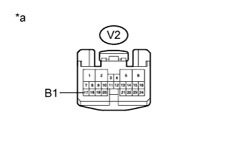 |
Disconnect the V2 multiplex network door ECU connector.
Measure the voltage according to the value(s) in the table below.
| Tester Connection | Condition | Specified Condition |
| V2-17 (B1) - Body ground | Always | 11 to 14 V |
| *a | Front view of wire harness connector (to Multiplex Network Door ECU) |
|
| ||||
| OK | |
 |
| 3.CHECK HARNESS AND CONNECTOR (SPOT LIGHT ASSEMBLY - MULTIPLEX NETWORK DOOR ECU) |
Disconnect the W12 or W7 spot light connector.
Disconnect the W10 multiplex network door ECU connector.
Measure the resistance according to the value(s) in the table below.
| Tester Connection | Condition | Specified Condition |
| W12-1 (B) - W10-25 (B2) | Always | Below 1 Ω |
| W12-3 (CTY) - W10-22 (LGLP) | Always | Below 1 Ω |
| W12-2 (E) - W10-19 (E1) | Always | Below 1 Ω |
| W12-1 (B) - Body ground | Always | 10 kΩ or higher |
| W12-3 (CTY) - Body ground | Always | 10 kΩ or higher |
| W12-2 (E) - Body ground | Always | 10 kΩ or higher |
| Tester Connection | Condition | Specified Condition |
| W7-1 (B) - W10-26 (B3) | Always | Below 1 Ω |
| W7-3 (CTY) - W10-23 (LGP2) | Always | Below 1 Ω |
| W7-2 (E) - W10-20 (E2) | Always | Below 1 Ω |
| W7-1 (B) - Body ground | Always | 10 kΩ or higher |
| W7-3 (CTY) - Body ground | Always | 10 kΩ or higher |
| W7-2 (E) - Body ground | Always | 10 kΩ or higher |
|
| ||||
| OK | ||
| ||
| ||

