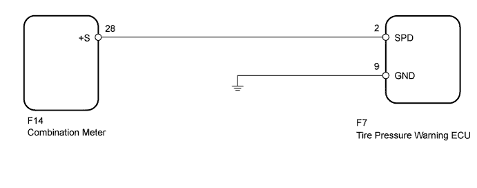
DTC C2191/91 Vehicle Speed Signal Error (Test Mode DTC) |
| DTC Code | Detection Condition | Trouble Area |
| C2191/91 | The test mode procedure is performed. |
|
| 1.READ VALUE USING TECHSTREAM (VEHICLE SPEED) |
Turn the ignition switch off.
Connect the Techstream to the DLC3.
Turn the ignition switch to ON.
Turn the Techstream on.
Enter the following menus: Chassis / Tire Pressure Monitor / Data List.
Check that the values indicated on the Techstream and on the combination meter are the same.
| Tester Display | Measurement Item/Range | Normal Condition | Diagnostic Note |
| Vehicle Speed | Vehicle speed/ min.: 0 km/h (0 mph) max.: 255 km/h (158 mph) | Almost same as actual vehicle speed | The speed indicated on the combination meter. |
|
| ||||
| OK | ||
 | ||
| ||
| 2.INSPECT TIRE PRESSURE WARNING ECU (SPD SIGNAL) |
Disconnect the F7 ECU connector.
Jack up the vehicle.
Move the shift the lever to N.
Turn the ignition switch to ON.
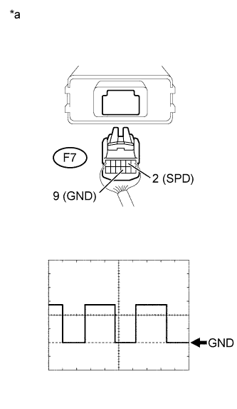 |
Check the waveform of the ECU connector using an oscilloscope while turning any of the wheels slowly.
| Tester Connection | Switch Condition | Specified Condition |
| F7-2 (SPD) - F7-9 (GND) | Ignition switch ON | Correct waveform is as shown |
| Item | Contents |
| Tool Setting | 5 V/DIV., 20 ms/DIV. |
| Vehicle Condition | Any wheel is rotated slowly |
| *a | Rear view of wire harness connector (to Tire Pressure Warning ECU) |
|
| ||||
| OK | ||
| ||
| ||
| 3.CHECK HARNESS AND CONNECTOR (ECU - COMBINATION METER) |
Disconnect the F7 ECU connector.
Disconnect the F14 meter connector.
Measure the resistance according to the value(s) in the table below.
| Tester Connection | Condition | Specified Condition |
| F7-2 (SPD) - F14-28 (+S) | Always | Below 1 Ω |
| F7-2 (SPD) - Body ground | Always | 10 kΩ or higher |
|
| ||||
| OK | ||
| ||
| ||

