Home › Vehicle Interior › METER / GAUGE / DISPLAY › CLOCK SYSTEM

CLOCK SYSTEM > TERMINALS OF ECU

for Preparation Click here


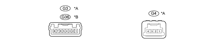
ACCESSORY METER ASSEMBLY

E239700E01


Text in Illustration 
*A
w/ CRAWL Control
*B
w/o CRAWL Control
  1. Measure the voltage and resistance according to the value(s) in the table below.

    w/ CRAWL Control 
    Terminal No. (Symbol)
    Wiring Color
    Terminal Description
    Condition
    Specified Condition
    G3-1 (E) - Body ground
    W-B - Body ground
    Ground
    Always
    Below 1 Ω
    G3-4 (DAT2) - Body ground
    LG - Body ground
    LIN communication signal
    Ignition switch ON
    Pulse generation
    G3-5 (IG+) - Body ground
    L - Body ground
    Ignition switch signal
    Ignition switch off
    Below 1 V
    Ignition switch ON
    11 to 14 V
    G3-6 (ACC) - Body ground
    P - Body ground
    Ignition switch signal
    Ignition switch off
    Below 1 V
    Ignition switch ACC
    11 to 14 V
    G3-7 (B) - Body ground
    L - Body ground
    Battery
    Always
    11 to 14 V
    G4-1 (ILL+) - Body ground
    G - Body ground
    Illumination signal
    Light control switch in tail or head position
    11 to 14 V
    G4-4 (ILL-) - Body ground
    GR - Body ground
    Illumination signal
    Light control switch off
    Below 1 V
    Ignition switch ON, light control switch in tail or head position
    Pulse generation

    w/o CRAWL Control 
    Terminal No. (Symbol)
    Wiring Color
    Terminal Description
    Condition
    Specified Condition
    G36-1 (B) - Body ground
    L - Body ground
    Battery
    Always
    11 to 14 V
    G36-2 (ACC) - Body ground
    P - Body ground
    Ignition switch signal
    Ignition switch off
    Below 1 V
    Ignition switch ACC
    11 to 14 V
    G36-3 (ILL+) - Body ground
    G - Body ground
    Illumination signal
    Light control switch in tail or head position
    11 to 14 V
    G36-7 (E) - Body ground
    W-B - Body ground
    Ground
    Always
    Below 1 Ω