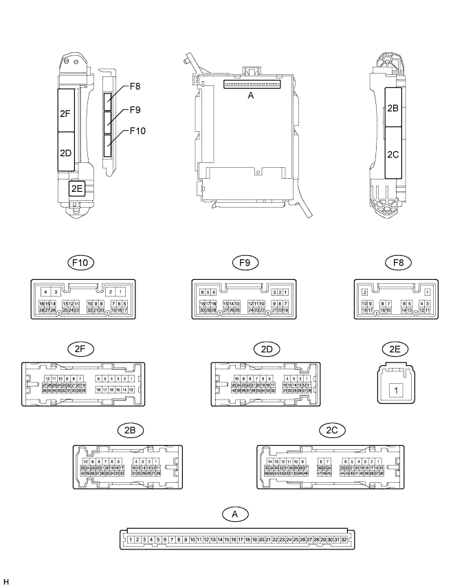
AUTOMATIC RUNNING BOARD SYSTEM > TERMINALS OF ECU |
| CHECK DRIVER SIDE JUNCTION BLOCK ASSEMBLY AND MAIN BODY ECU (MULTIPLEX NETWORK BODY ECU) |
Measure the voltage according to the value(s) in the table below.
| Terminal No. (Symbol) | Wiring Color | Terminal Description | Condition | Specified Condition |
| F9-15 (SPD) - 2B-4 (GND1) | R - W-B | Speed signal | Vehicle speed at lower than 8 km/h (5 mph) | 11 to 14 V |
| Vehicle speed at 8 km/h (5 mph) or more | Below 1 V |
| CHECK SIDE AUTO STEP CONTROLLER ECU ASSEMBLY |
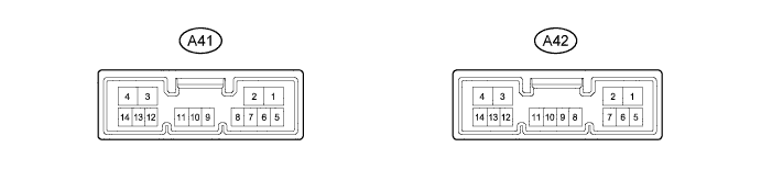
Disconnect the A41 side auto step controller ECU assembly connector.
Measure the voltage and resistance according to the value(s) in the table below.
| Terminal No. (Symbol) | Wiring Color | Terminal Description | Condition | Specified Condition |
| A41-1 (GND) - Body Ground | W-B - Body Ground | Ground | Always | Below 1 Ω |
| A41-4 (B) - A41-1 (GND) | L - W-B | Battery power supply | Always | 11 to 14 V |
Reconnect the A41 side auto step controller ECU assembly connector.
Measure the voltage and resistance according to the value(s) in the table below.
| Terminal No. (Symbol) | Wiring Color | Terminal Description | Condition | Specified Condition |
| A41-5 (SSR-) - A41-1 (GND) | GR - W-B | Ground | Always | Below 1 Ω |
| A41-9 (SSR2) - A41-1 (GND) | L - W-B | Side auto step motor hall sensor RH signal | When the automatic running board RH is being deployed or stowed | Pulse generation (See waveform 1) |
| A41-10 (SSR1) - A41-1 (GND) | W - W-B | Side auto step motor hall sensor LH signal | When the automatic running board LH is being deployed or stowed | Pulse generation (See waveform 1) |
| A41-14 (SSR+) - A41-1 (GND) | LG - W-B | Side auto step hall sensor power supply | When the automatic running board is being deployed or stowed | 8 to 11 V |
| A42-1 (DPL2) - A41-1 (GND) | G - W-B | Side auto step motor RH operation signal | Passenger side door is opened When the automatic running board RH is being deployed | 11 to 14 V |
| A42-2 (STW2) - A41-1 (GND) | R - W-B | Side auto step motor RH operation signal | Passenger side door is closed When the automatic running board RH is being stowed | 11 to 14 V |
| A42-3 (STW1) - A41-1 (GND) | P - W-B | Side auto step motor LH operation signal | Driver side door is closed When the automatic running board LH is being stowed | 11 to 14 V |
| A42-4 (DPL1) - A41-1 (GND) | V - W-B | Side auto step motor LH operation signal | Driver side door is opened When the automatic running board LH is being deployed | 11 to 14 V |
| A42-9 (FOUT) - A41-1 (GND) | GR - W-B | Ground | Always | Below 1 V |
| A42-10 (FIN) - A41-1 (GND) | W - W-B | Ground | Always | Below 1 V |
| A42-11 (SP1+) - A41-1 (GND) | R - W-B | Speed signal | Vehicle speed at lower than 8 km/h (5 mph) | 11 to 14 V |
| Vehicle speed at 8 km/h (5 mph) or more | Below 1 V | |||
| A42-12 (IND) - A41-1 (GND) | G - W-B | Warning light drive output | Warning light on | 11 to 14 V |
| Warning light off | Below 1 V | |||
| A42-13 (CTY2) - A41-1 (GND) | R - W-B | Door courtesy light switch RH signal | Rear door RH open | Below 1 V |
| Rear door RH closed | 11 to 14 V | |||
| A42-14 (CTY1) - A41-1 (GND) | L - W-B | Door courtesy light switch LH signal | Rear door LH open | Below 1 V |
| Rear door LH closed | 11 to 14 V |
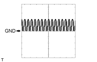 |
Using an oscilloscope, check the waveform 1.
| Item | Content |
| Tool Setting | 5 V/DIV., 5 ms/DIV. |
| Condition | When the automatic running board is being deployed or stowed |