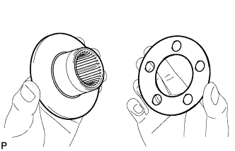
REAR DIFFERENTIAL CARRIER ASSEMBLY (w/ Differential Lock) > REASSEMBLY |
| 1. INSTALL DIFFERENTIAL CASE ASSEMBLY |
|
Install the rear differential side gear thrust washer to the rear differential side gear.
Install the rear differential pinion thrust washer and rear differential pinion to the rear differential spider.
Fix the differential case RH in place.
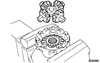 |
Install the rear differential side gear and rear differential spider to the differential case RH.
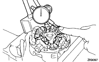 |
Using a dial indicator, measure the differential case RH side backlash while pushing the pinion toward the case.
Remove the rear differential spider from the differential case RH.
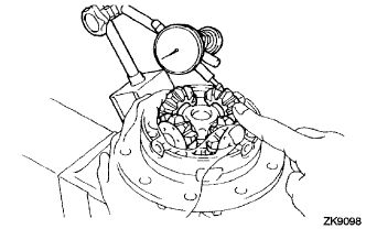 |
Install the rear differential side gear and rear differential spider to the differential case LH.
Using a dial indicator, measure the differential case LH side backlash while pushing the pinion toward the case.
| Specified Condition | Specified Condition |
| 0.88 to 0.92 mm (0.0346 to 0.0362 in.) | 1.18 to 1.22 mm (0.465 to 0.0480 in.) |
| 0.98 to 1.02 mm (0.0386 to 0.0402 in.) | 1.28 to 1.32 mm (0.0504 to 0.00520 in.) |
| 1.08 to 1.12 mm (0.0425 to 0.0441 in.) | - |
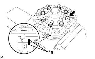 |
Align the matchmarks and assemble the differential case from the RH and LH cases.
| *a | Matchmark |
Using a plastic-faced hammer, install the differential case.
Install the 8 bolts.
| 2. INSTALL DIFFERENTIAL RING GEAR |
Clean the contact surfaces of the differential case and ring gear.
Heat the ring gear to approximately 100°C (212°F) in boiling water.
Carefully take the ring gear out of the boiling water.
After the moisture on the ring gear has completely evaporated, quickly install the ring gear to the differential case.
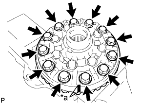 |
Align the matchmarks on the ring gear and differential case.
| *a | Matchmark |
| *1 | Lock Plate |
After the ring gear cools down sufficiently, apply adhesive to the 12 bolts and install them.
| 3. INSTALL REAR DIFFERENTIAL CASE BEARING |
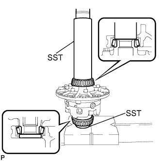 |
Using SST and a press, install the bearing to the differential case.
| 4. INSPECT DIFFERENTIAL RING GEAR RUNOUT |
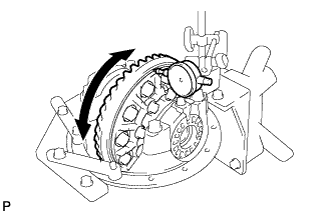 |
Install the differential case to the carrier, and then install the 2 adjusting nuts so that there is no play in the bearing.
Install the 2 bearing caps with the 4 bolts.
Using a dial indicator, measure the runout of the ring gear.
Remove the 2 bearing caps, 2 adjusting nuts and differential case.
| 5. INSTALL REAR DRIVE PINION FRONT TAPERED ROLLER BEARING |
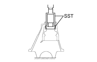 |
Using SST and a press, install the tapered roller bearing to the carrier.
| 6. INSTALL REAR DRIVE PINION REAR TAPERED ROLLER BEARING (OUTER) |
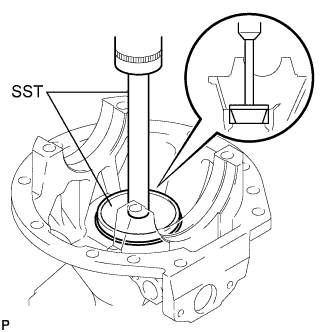 |
Install the plate washer to the carrier.
Using SST and a press, install the tapered roller bearing to the carrier.
| 7. INSTALL REAR DRIVE PINION REAR TAPERED ROLLER BEARING (INNER) |
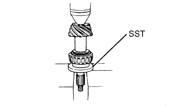 |
Using SST and a press, install the tapered roller bearing to the drive pinion.
| 8. ADJUST DIFFERENTIAL DRIVE PINION PRELOAD |
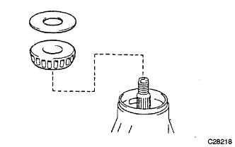 |
Install the drive pinion, rear drive pinion tapered roller bearing and rear differential drive oil slinger.
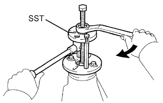 |
Using SST, install the drive pinion companion flange.
Coat the threads of the nut with hypoid gear oil LSD.
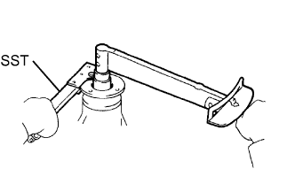 |
Using SST to hold the drive pinion companion flange, tighten the nut.
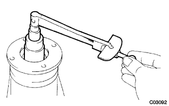 |
Using a torque wrench, measure the preload.
| Item | Specified Condition |
| New Bearing | 0.83 to 2.18 N*m (8.64 to 22.2 kgf*cm, 7.35 to 19.3 in.*lbf) |
| Used Bearing | 0.88 to 1.98 N*m (8.97 to 20.2 kgf*cm, 7.79 to 17.5 in.*lbf) |
| 9. INSTALL DIFFERENTIAL CASE ASSEMBLY |
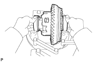 |
Place the 2 bearing outer races on their respective bearings.
| 10. INSTALL REAR DIFFERENTIAL BEARING ADJUSTING NUT |
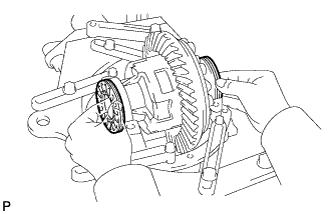 |
Install the 2 adjusting nuts to the carrier, making sure the nuts are threaded properly.
| 11. INSPECT AND ADJUST DIFFERENTIAL RING GEAR AND DIFFERENTIAL DRIVE PINION BACKLASH |
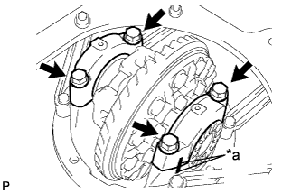 |
Align the matchmarks on the cap and carrier.
| *a | Matchmark |
Install the right and left bearing caps with the 4 bolts.
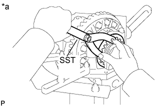 |
Tighten the 4 bearing cap bolts to the specified torque, and then loosen them to the point where the adjusting nuts can be turned by SST.
| *a | for LH Side |
Using SST, tighten the adjusting nut on the ring gear side until the ring gear has a backlash of about 0.2 mm (0.008 in.).
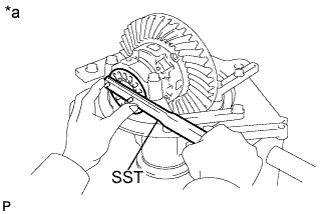 |
While turning the ring gear, use SST to tighten the adjusting nut on the drive pinion side.
| *a | for RH Side |
Using SST, tighten the adjusting nut 1 to 1.5 notches from the 0 preload position.
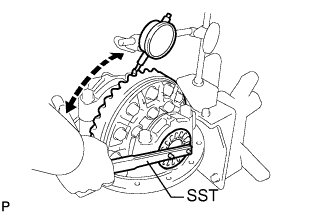 |
Using a dial indicator, adjust the ring gear backlash until it is within the specification.
|
Tighten the bearing cap bolts.
| *a | Matchmark |
| 12. INSPECT TOTAL PRELOAD |
|
Using a torque wrench, measure the preload with the teeth of the drive pinion and ring gear in contact.
| 13. INSPECT TOOTH CONTACT BETWEEN RING GEAR AND DRIVE PINION |
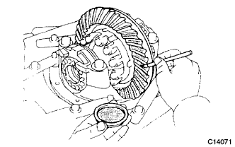 |
Coat 3 or 4 teeth at 3 different positions on the ring gear with Prussian blue.
Hold the companion flange firmly and rotate the ring gear in both directions.
Inspect the tooth contact pattern.
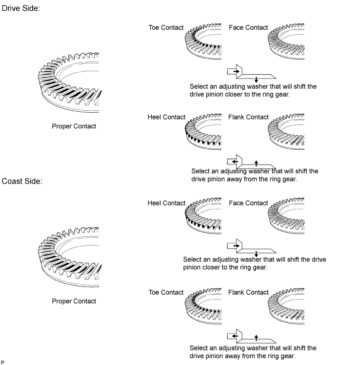
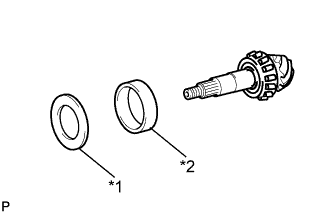 |
| *1 | Plate Washer |
| *2 | Rear Drive Pinion Rear Tapered Roller Bearing (Outer) |
| Specified Condition | Specified Condition |
| 1.845 to 1.855 mm (0.0726 to 0.0730 in.) | 2.085 to 2.095 mm (0.0821 to 0.0825 in. ) |
| 1.855 to 1.865 mm (0.0730 to 0.0734 in.) | 2.095 to 2.105 mm (0.0825 to 0.0829 in.) |
| 1.865 to 1.875 mm (0.0734 to 0.0738 in.) | 2.105 to 2.115 mm (0.0829 to 0.0833 in.) |
| 1.875 to 1.885 mm (0.0738 to 0.0742 in.) | 2.115 to 2.125 mm (0.0833 to 0.0837 in.) |
| 1.885 to 1.895 mm (0.0742 to 0.0746 in.) | 2.125 to 2.135 mm (0.0837 to 0.0841 in.) |
| 1.895 to 1.905 mm (0.0746 to 0.0750 in.) | 2.135 to 2.145 mm (0.0841 to 0.0844 in.) |
| 1.905 to 1.915 mm (0.0750 to 0.0754 in.) | 2.145 to 2.155 mm (0.0844 to 0.0848 in.) |
| 1.915 to 1.925 mm (0.0754 to 0.0758 in.) | 2.155 to 2.165 mm (0.0848 to 0.0852 in.) |
| 1.925 to 1.935 mm (0.0758 to 0.0762 in.) | 2.165 to 2.175 mm (0.0852 to 0.0856 in.) |
| 1.935 to 1.945 mm (0.0762 to 0.0766 in.) | 2.175 to 2.185 mm (0.0856 to 0.0860 in.) |
| 1.945 to 1.955 mm (0.0766 to 0.0770 in.) | 2.185 to 2.195 mm (0.0860 to 0.0864 in.) |
| 1.955 to 1.965 mm (0.0770 to 0.0774 in.) | 2.195 to 2.205 mm (0.0864 to 0.0868 in.) |
| 1.965 to 1.975 mm (0.0774 to 0.0778 in.) | 2.205 to 2.215 mm (0.0868 to 0.0872 in.) |
| 1.975 to 1.985 mm (0.0778 to 0.0781 in.) | 2.215 to 2.225 mm (0.0872 to 0.0876 in.) |
| 1.985 to 1.995 mm (0.0781 to 0.0785 in.) | 2.225 to 2.235 mm (0.0876 to 0.0880 in.) |
| 1.995 to 2.005 mm (0.0785 to 0.0789 in.) | 2.235 to 2.245 mm (0.0880 to 0.0884 in.) |
| 2.005 to 2.015 mm (0.0789 to 0.0793 in.) | 2.245 to 2.255 mm (0.0884 to 0.0888 in.) |
| 2.015 to 2.025 mm (0.0793 to 0.0797 in.) | 2.255 to 2.265 mm (0.0888 to 0.0892 in.) |
| 2.025 to 2.035 mm (0.0797 to 0.0801 in.) | 2.265 to 2.275 mm (0.0892 to 0.0896 in.) |
| 2.035 to 2.045 mm (0.0801 to 0.0805 in.) | 2.275 to 2.285 mm (0.0896 to 0.0900 in. ) |
| 2.045 to 2.055 mm (0.0805 to 0.0809 in.) | 2.285 to 2.295 mm (0.0900 to 0.0904 in.) |
| 2.055 to 5.065 mm (0.0809 to 0.0813 in.) | 2.295 to 2.305 mm (0.0904 to 0.0907 in.) |
| 2.065 to 2.075 mm (0.0813 to 0.0817 in.) | 2.305 to 2.315 mm (0.0907 to 0.0911 in.) |
| 2.075 to 2.085 mm (0.0817 to 0.0821 in.) | - |
| 14. REMOVE REAR DRIVE PINION NUT |
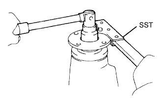 |
Using SST to hold the drive pinion companion flange, remove the nut.
| 15. REMOVE REAR DRIVE PINION COMPANION FLANGE SUB-ASSEMBLY |
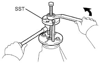 |
Using SST, remove the drive pinion companion flange.
| 16. REMOVE REAR DIFFERENTIAL DRIVE PINION OIL SLINGER |
| 17. REMOVE REAR DRIVE PINION FRONT TAPERED ROLLER BEARING (INNER) |
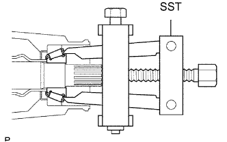 |
Using SST, remove the rear drive pinion tapered roller bearing (inner).
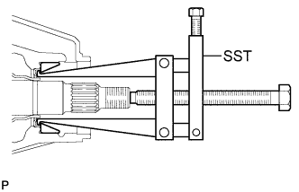 |
Using SST, tap out the rear drive pinion tapered roller bearing (outer).
| 18. REMOVE REAR DRIVE PINION FRONT TAPERED ROLLER BEARING (OUTER) |
| 19. INSTALL REAR DIFFERENTIAL DRIVE PINION BEARING SPACER |
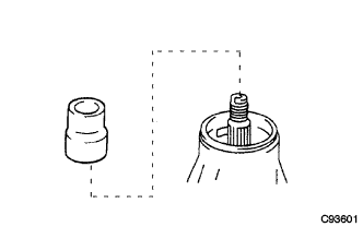 |
Install a new bearing spacer to the drive pinion.
| 20. INSTALL DIFFERENTIAL OIL STORAGE RING |
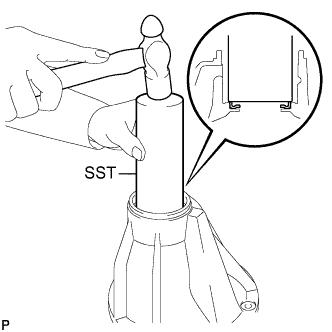 |
Using SST, tap in a new oil storage ring.
| 21. INSTALL REAR DRIVE PINION FRONT TAPERED ROLLER BEARING |
| 22. INSTALL REAR DIFFERENTIAL DRIVE PINION OIL SLINGER |
| 23. INSTALL REAR DIFFERENTIAL CARRIER OIL SEAL |
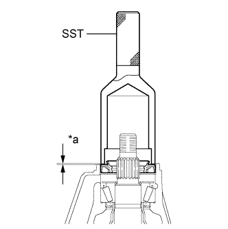 |
Apply MP grease to the oil seal lip.
Using SST and a hammer, install a new carrier oil seal.
| *a | Oil Seal Depth |
| 24. INSTALL REAR DRIVE PINION COMPANION FLANGE SUB-ASSEMBLY REAR |
|
Using SST, install the drive pinion companion flange to the drive pinion.
|
Coat the threads of a new nut with hypoid gear oil.
Using SST to hold the flange, tighten the nut.
| 25. INSPECT DRIVE PINION PRELOAD |
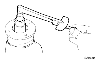 |
Using a torque wrench, measure the preload of the backlash between the drive pinion and ring gear.
| Item | Specified Condition |
| New Bearing | 0.83 to 2.18 N*m (8.64 to 22.2 kgf*cm, 7.35 to 19.3 in.*lbf) |
| Reused Bearing | 0.88 to 1.98 N*m (8.97 to 20.2 kgf*cm, 7.79 to 17.5 in.*lbf) |
| 26. INSPECT TOTAL PRELOAD |
|
Using a torque wrench, measure the preload.
| 27. INSPECT DIFFERENTIAL RING GEAR BACKLASH |
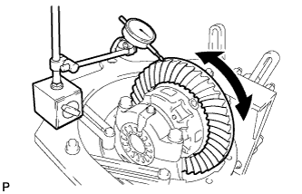 |
Using a dial indicator, check the backlash of the ring gear.
| 28. INSPECT RUNOUT OF REAR DRIVE PINION COMPANION FLANGE SUB-ASSEMBLY REAR |
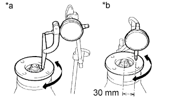 |
Using a dial indicator, measure the runout of the drive pinion companion flange vertically and laterally.
| Item | Specified Condition |
| Vertical runout | 0.14 mm (0.00551 in.) |
| Lateral runout | 0.14 mm (0.00551 in.) |
| *a | Vertical Runout |
| *b | Lateral Runout |
| 29. INSTALL REAR DRIVE PINION NUT |
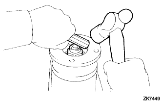 |
Using a chisel and hammer, stake the drive pinion nut.
| 30. INSTALL REAR DIFFERENTIAL BEARING ADJUSTING NUT LOCK |
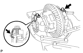 |
Install 2 new adjusting nut locks to the bearing caps with the 2 bolts.
After tightening the bolts, bend the nut locks.
| 31. INSTALL REAR DIFFERENTIAL LOCK SHIFT FORK |
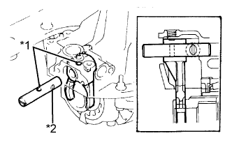 |
Apply MP grease to shaft.
Install the fork shaft so that the hole of the shift fork shaft aligns with that of the shift fork.
| *1 | Holes |
| *2 | Groove |
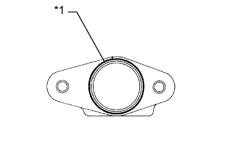 |
Remove any FIPG material and be careful not to drop the oil shaft retainer.
Apply seal packing to the carrier as shown in the illustration.
| *1 | Seal Packing |
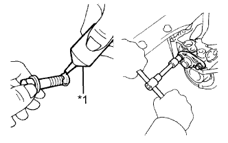 |
Clean the threads of the bolts and retainer bolt holes with toluene or trichloroethylene.
Apply adhesive to 2 or 3 threads at the tip of each mount bolt.
| *1 | Adhesive |
Install the shaft retainer with the 2 bolts.
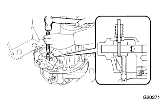 |
Using a 5 mm pin punch and hammer, install the slotted spring pin to the shift fork.
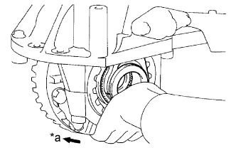 |
Push the differential lock sleeve in deeply and hold it in position.
| *a | Lock |
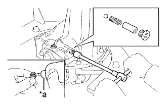 |
Install the ball, spring and spring seat.
Clean the threads of the 2 plugs and plug holes with toluene or trichloroethylene.
| *1 | Adhesive |
Using a 6 mm hexagon wrench, install the screw plugs.
| 32. INSTALL DIFFERENTIAL LOCK INDICATOR SWITCH |
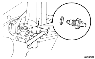 |
Install the indicator switch together with a new gasket.
| 33. INSPECT REAR DIFFERENTIAL LOCK SLEEVE |
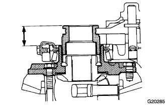 |
Measure the distance between the sleeve and tip of the differential case when the differential is free, and when it is locked.
| 34. INSTALL DIFFERENTIAL LOCK SHIFT ACTUATOR |
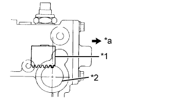 |
Check that the outermost rack tooth of the shift fork is approximately above the center line of the actuator installation hole.
| *a | Outside |
| *1 | Shift Fork |
| *2 | Actuator Installation Hole |
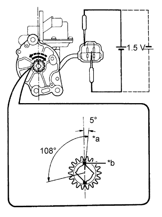 |
Make sure that the matchmarks on the pinion of the actuator are in the range of 0 to 5 degrees clockwise from the center line of the actuator.
| *a | Matchmark |
| *b | Groove |
Install a new O-ring to the actuator.
Apply a light coat of gear oil to the O-ring.
Apply MP grease to the gear.
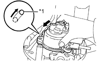 |
Mack sure that the outermost rack tooth of the shift fork aligns with the matchmarks on the pinion of the actuator.
Install the actuator so that the knock pin on the carrier side fits into the long hole on the actuator side.
| *1 | Knock Pin |
Rotate the actuator counterclockwise so that the knock pin slides to the end of the hole as shown in the illustration.
Install the bolts.