 |
Prepare the vehicle according to the following conditions:
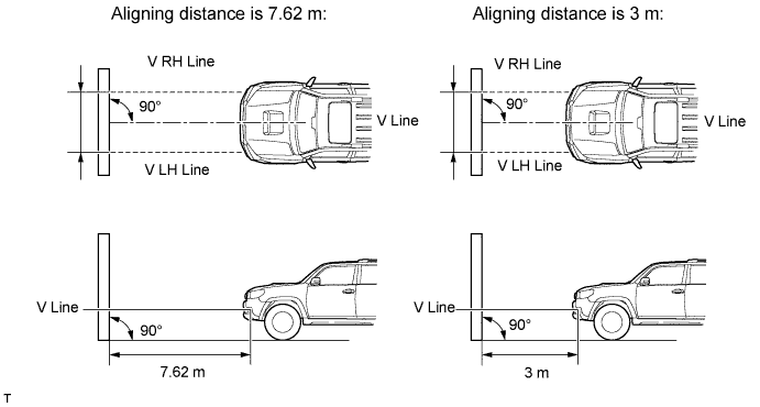
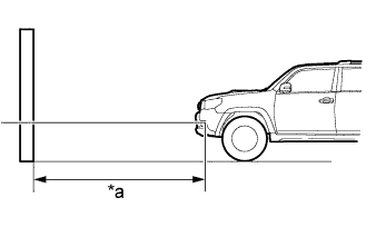
| *a | 7.62 or 3 m |
- Move the vehicle to a location that is sufficiently dark so that the headlight cutoff line can be visually checked. The cutoff line is an imaginary plane below which headlight light is projected and above which light is not projected.
- Move the vehicle to a level surface.
- Point the front of the vehicle at a wall. The wall must be perpendicular to the surface that the vehicle is on.
- Position the vehicle 7.62 m (25 ft.) from the wall.
- Push down on the vehicle several times to settle the suspension.
- HINT:
- A distance of 7.62 m (25 ft.) between the vehicle and wall is necessary for proper aim adjustment. If unavailable, secure a distance of exactly 3 m (9.8 ft.). View the part of the illustration below applicable to the distance from the vehicle to the wall.
- NOTICE:
- Be careful not to damage the suspension.