DIFFERENTIAL SYSTEM > INSPECTION |
| 1. INSPECT DIFFERENTIAL LOCK SYSTEM |
|
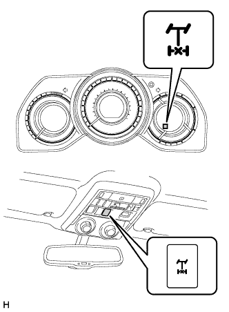
Inspect the indicator light.
Check that the indicator light lights up approximately 1 second after the ignition switch is turned ON.
Inspect the differential lock operation.
Jack up the vehicle and start the engine.
Set the transfer to L4.
When the differential lock control switch is set to the ON position, check that the indicator light turns on. Differential lock is applied to the rear wheels at this time.
When the differential lock control switch is in the OFF position, check that the indicator light goes off. The rear differential lock is released at this time.
Stop the engine and lower the vehicle.
| 2. INSPECT FOUR WHEEL DRIVE CONTROL ECU (POWER SUPPLY) |
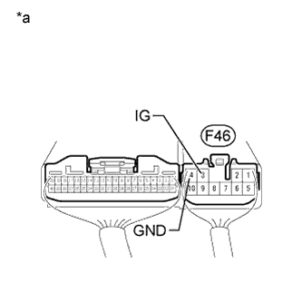 |
Check the harness and connector (ECU - battery and body ground).
Measure the voltage according to the value(s) in the table below.
| Tester Connection | Switch Condition | Specified Condition |
| F46-3 (IG) - Body ground | Ignition switch ON | 11 to 14 V |
| *a | Component with harness connected (Four Wheel Drive Control ECU) |
Measure the resistance according to the value(s) in the table below.
| Tester Connection | Condition | Specified Condition |
| F46-10 (GND) - Body ground | Always | Below 1 Ω |
| 3. INSPECT DIFFERENTIAL LOCK SWITCH |
Check the harness and connector (differential lock switch - ECU).
Disconnect the F47 ECU connector.
Disconnect the U5 switch connector.
Measure the resistance according to the value(s) in the table below.
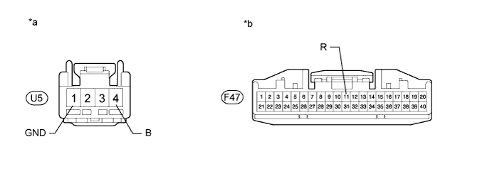
| *a | Front view of wire harness connector (to Differential Lock Switch) | *b | Front view of wire harness connector (to Four Wheel Drive Control ECU) |
| Tester Connection | Condition | Specified Condition |
| U5-4 (B) - F47-11 (R) | Always | Below 1 Ω |
| U5-1 (GND) - Body ground | Always | Below 1 Ω |
| U5-1 (GND) - F47-11 (R) | Always | 100 kΩ or higher |
Check the differential lock switch.
Turn the ignition switch off.
Connect the U5 switch connector.
Connect the F47 ECU connector.
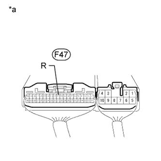 |
Measure the resistance according to the value(s) in the table below.
| Tester Connection | Switch Condition | Specified Condition |
| F47-11 (R) - Body ground | Differential lock switch on | Below 1.5 V |
| Differential lock switch off | 11 to 14 V |
| *a | Component with harness connected (Four Wheel Drive Control ECU) |
| 4. INSPECT REAR DIFFERENTIAL LOCK ACTUATOR |
Check the harness and connector (rear differential lock actuator - ECU).
Disconnect the D2 differential lock actuator connector.
Disconnect the F47 and F46 ECU connectors.
Measure the resistance according to the value(s) in the table below.
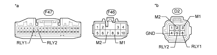
| *a | Front view of wire harness connector (to Four Wheel Drive Control ECU) | *b | Front view of wire harness connector (to Differential Lock Actuator) |
| Tester Connection | Condition | Specified Condition |
| F47-7 (RLY2) - D2-5 (RLY2) | Always | Below 1 Ω |
| F47-7 (RLY2) - Body ground | Always | 100 kΩ or higher |
| F47-6 (RLY1) - D2-6 (RLY1) | Always | Below 1 Ω |
| F47-6 (RLY1) - Body ground | Always | 100 kΩ or higher |
| F46-7 (M2) - D2-2 (M2) | Always | Below 1 Ω |
| F46-7 (M2) - Body ground | Always | 100 kΩ or higher |
| F46-8 (M1) - D2-3 (M1) | Always | Below 1 Ω |
| F46-8 (M1) - Body Ground | Always | 100 kΩ or higher |
| D2-4 (GND) - Body Ground | Always | Below 1 Ω |
Check the free to lock switch.
Connect lines via a relay as shown in the illustration and check that the actuator fork moves from the free to the lock position.
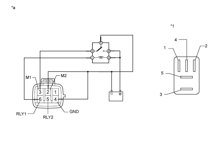
| *1 | Stop LP Relay | - | - |
| *a | Front view of wire harness connector (to Differential Lock Actuator) | - | - |
After the free to lock switch is complete, check the limit switch.
Measure the resistance according to the value(s) in the table below.
| Tester Connection | Condition | Specified Condition |
| 5 (RLY2) - 4 (GND) | After free to lock switch is complete | Below 12.5 Ω |
| 6 (RLY1) - 4 (GND) | After free to lock switch is complete | 500 kΩ or higher |
Check the lock to free switch.
Connect lines via a relay as shown in the illustration and check that the actuator fork moves from the lock to the free position.
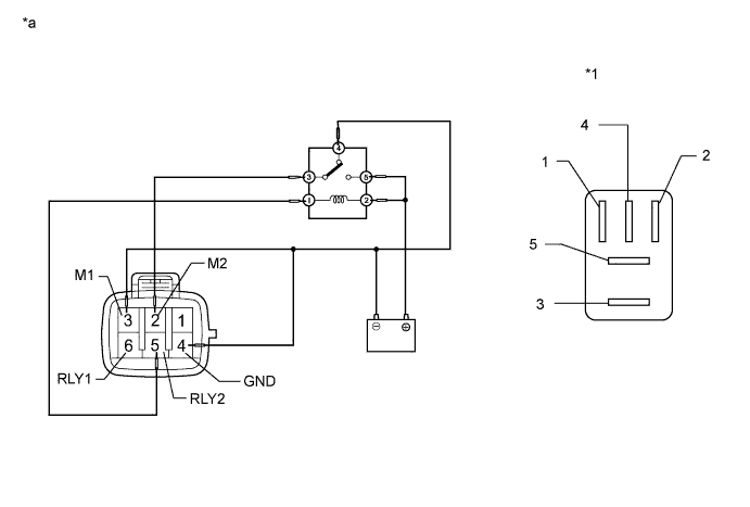
| *1 | Stop LP Relay | - | - |
| *a | Front view of wire harness connector (to Differential Lock Actuator) | - | - |
After the lock to free switch is complete, check the limit switch.
Measure the resistance according to the value(s) in the table below.
| Tester Connection | Condition | Specified Condition |
| 5 (RLY2) - 4 (GND) | After lock to free switch is complete | 500 kΩ or higher |
| 6 (RLY1) - 4 (GND) | After lock to free switch is complete | Below 12.5 Ω |
| 5. INSPECT DIFFERENTIAL LOCK POSITION SWITCH |
Inspect the rear differential lock position switch.
Remove the rear differential lock position switch .
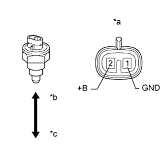 |
Measure the resistance according to the value(s) in the table below.
| Tester Connection | Switch Condition | Specified Condition |
| 2 (+B) - 1 (GND) | Pushed | Below 1 Ω |
| Released | 100 kΩ or higher |
| *a | Component without harness connected (Rear Differential Lock Position Switch) |
| *b | Pushed |
| *c | Released |
Check the harness and connector (ECU - differential lock position switch).
Disconnect the D3 differential lock position switch connector.
Disconnect the F47 ECU connector.
Measure the resistance according to the value(s) in the table below.
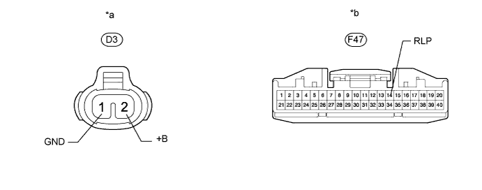
| *a | Component without harness connected (Rear Differential Lock Position Switch) | *b | Component without harness connected (Four Wheel Drive Control ECU) |
| Tester Connection | Condition | Specified Condition |
| F47-14 (RLP) - D3-2 (+B) | Always | Below 1 Ω |
| F47-14 (RLP) - Body ground | Always | 100 kΩ or higher |
| D3-1 (GND) - Body ground | Always | Below 1 Ω |
| 6. INSPECT AUTOMATIC DISCONNECTING DIFFERENTIAL ACTUATOR |
Check the free to lock switch.
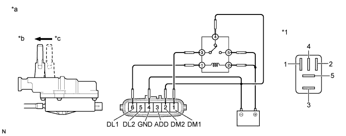
| *1 | Stop LP Relay | - | - |
| *a | Component without harness connected (A.D.D. Actuator Connector) | *b | Lock |
| *c | Free | - | - |
Connect lines via a relay as shown in the illustration and check that the actuator fork moves from the free to the lock position.
After the free to lock switch is complete, inspect the A.D.D. detection switch and limit switch.
| Tester Connection | Condition | Specified Condition |
| 3 (ADD) - 4 (GND) | After free to lock switch is complete | Below 12.5 Ω |
| 5 (DL2) - 4 (GND) | Below 12.5 Ω | |
| 6 (DL1) - 4 (GND) | 0.5 MΩ or higher |
Check the lock to free switch.
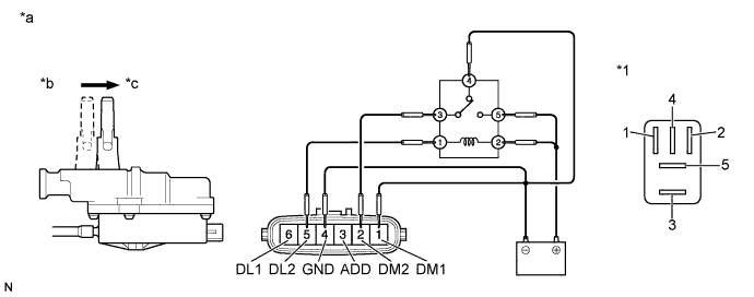
| *1 | Stop LP Relay | - | - |
| *a | Component without harness connected (A.D.D Actuator Connector) | *b | Lock |
| *c | Free | - | - |
Connect lines via a relay as shown in the illustration and check that the actuator fork moves from the lock to the free position.
After the lock to free switch is complete, inspect the A.D.D. detection switch and limit switch.
| Tester Connection | Condition | Specified Condition |
| 3 (ADD) - 4 (GND) | After lock to free switch is complete | 0.5 MΩ or higher |
| 5 (DL2) - 4 (GND) | 0.5 MΩ or higher | |
| 6 (DL1) - 4 (GND) | Below 12.5 Ω |