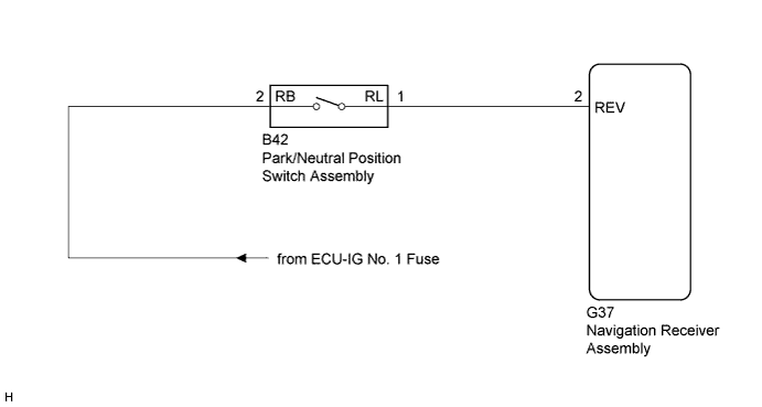
NAVIGATION SYSTEM > Reverse Signal Circuit |
| 1.CHECK VEHICLE SIGNAL (OPERATION CHECK) |
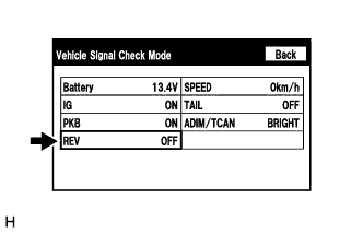 |
Enter the "Vehicle Signal Check Mode" screen. Refer to check Vehicle Signal in Operation Check (Click here).
Check that the display changes between ON and OFF according to the shift lever position.
| Shift Lever Position | Display |
| R | ON |
| Except R | OFF |
|
| ||||
| OK | ||
 | ||
| ||
| 2.CHECK HARNESS AND CONNECTOR (REVERSE SIGNAL) |
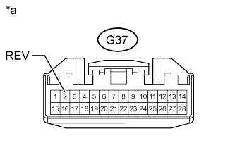 |
Disconnect the G37 navigation receiver assembly connector.
Measure the voltage according to the value(s) in the table below.
| Tester Connection | Condition | Specified Condition |
| G37-2 (REV) - Body ground | Ignition switch ON Shift lever in R | 11 to 14 V |
| Ignition switch ON Shift lever in any position other than R | Below 1 V |
| *a | Front view of wire harness connector (to Navigation Receiver Assembly) |
|
| ||||
| OK | ||
| ||
| ||
| 3.CHECK HARNESS AND CONNECTOR (NAVIGATION RECEIVER ASSEMBLY - PARK/NEUTRAL POSITION SWITCH ASSEMBLY) |
Disconnect the G37 navigation receiver assembly connector.
Disconnect the B42 park/neutral position switch assembly connector.
Measure the resistance according to the value(s) in the table below.
| Tester Connection | Condition | Specified Condition |
| G37-2 (REV) - B42-1 (RL) | Always | Below 1 Ω |
| G37-2 (REV) - Body ground | Always | 10 kΩ or higher |
|
| ||||
| OK | |
 |
| 4.CHECK HARNESS AND CONNECTOR (PARK/NEUTRAL POSITION SWITCH ASSEMBLY - BATTERY) |
Disconnect the B42 park/neutral position switch assembly connector.
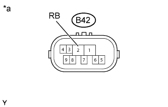 |
Measure the voltage according to the value(s) in the table below.
| Tester Connection | Switch Condition | Specified Condition |
| B42-2 (RB) - Body ground | Ignition switch ON | 11 to 14 V |
| *a | Component without harness connected (Park/neutral Position Switch Assembly) |
Proceed to the next step based on the check result.
| Result | Proceed to |
| NG | A |
| OK (for A750E) | B |
| OK (for A750F) | C |
|
| ||||
|
| ||||
| A | ||
| ||
| ||

