 |
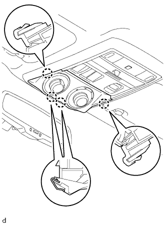
Detach the 4 claws to remove the drive monitor switch.
MANUAL(SOS)SWITCH > REMOVAL |
| 1. REMOVE DRIVE MONITOR SWITCH |
|
Detach the 4 claws to remove the drive monitor switch.
Disconnect the connector.
| 2. REMOVE MAP LIGHT ASSEMBLY |
Open the cover (w/o Drive Monitor Switch).
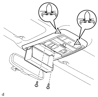 |
Remove the 2 screws.
Detach the 2 clips to remove the map light assembly.
Disconnect the connector.
| 3. REMOVE TELEPHONE SWITCH ASSEMBLY |
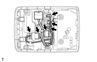 |
Disconnect the 6 connectors.
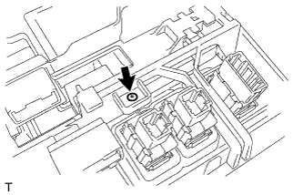 |
Remove the screw.
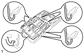 |
Detach the 8 claws and remove the inner bezel.
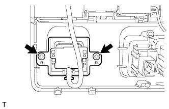 |
Remove the 2 screws and telephone switch.