FRONT EVAPORATOR TEMPERATURE SENSOR > REASSEMBLY |
| 1. INSTALL NO. 1 COOLER THERMISTOR |
|
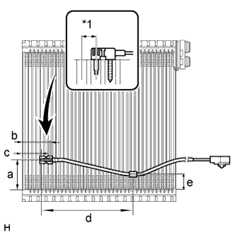
Insert the sensor to a location that is 1 fin to the right or left of its previous location.
| Item | Specified Condition |
| a | 50 mm (1.97 in.) |
| b | 46.7 mm (1.84 in.) |
| c | 33.3 mm (1.31 in.) |
| d | 154.1 mm (6.07 in.) |
| e | 25 mm (0.98 in.) |
| *1 | 1 Fin |
| 2. INSTALL NO. 1 COOLER EVAPORATOR SUB-ASSEMBLY |
Sufficiently apply compressor oil to 2 new O-rings and the fitting surface of the hose joint.
Install the 2 O-rings to the evaporator.
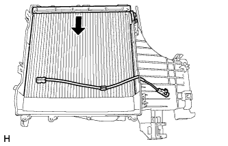 |
Install the evaporator.
Attach the 4 claws to install the unit case.
Install the 6 screws.
| 3. INSTALL DAMPER SERVO SUB-ASSEMBLY LH |
Align the grooves on the damper servo sub-assembly with the protrusions on the unit and install the damper servo sub-assembly.
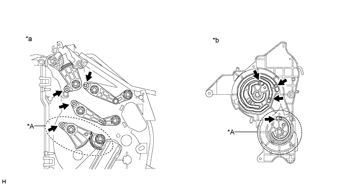
| *A | for Automatic Air Conditioning System | - | - |
| *a | Air Conditioning Unit Side | *b | Damper Servo Side |
Install the 4 screws.
| 4. INSTALL DAMPER SERVO SUB-ASSEMBLY RH |
Align the grooves on the damper servo sub-assembly with the protrusions on the unit and install the damper servo sub-assembly.
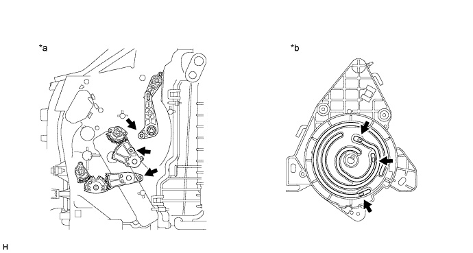
| *a | Air Conditioning Unit Side | *b | Damper Servo Side |
Install the 3 screws.
| 5. INSTALL COOLER EXPANSION VALVE |
Install the expansion valve.
| 6. INSTALL AIR CONDITIONING TUBE AND ACCESSORY ASSEMBLY |
Sufficiently apply compressor oil to 2 new O-rings and the fitting surface of the hose joint.
Install the 2 O-rings to the air conditioning tube and accessory assembly.
Install the air conditioning tube and accessory assembly.
Using a 4 mm hexagon wrench, install the 2 hexagon bolts.
Install new butyl tape.
Install new packing.
| 7. INSTALL AIR CONDITIONING HARNESS |
Attach the clamps to install the harness.
Connect the connectors.
| 8. INSTALL HEATER RADIATOR UNIT SUB-ASSEMBLY |
Install the radiator.
Install the bracket with the 2 screws.
| 9. INSTALL QUICK HEATER ASSEMBLY (w/ PTC Heater) |
Attach the 2 clamps to install the quick heater.
Install the 2 screws.
| 10. INSTALL DRAIN COOLER HOSE |
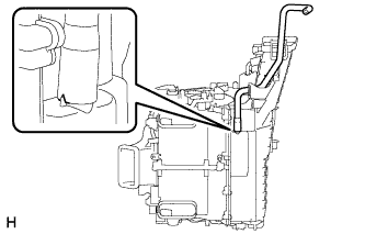 |
Install the drain cooler hose as shown in the illustration.
| 11. INSTALL ASPIRATOR HOSE |
Attach the 2 claws to install the aspirator hose.
| 12. INSTALL DEFROSTER NOZZLE ASSEMBLY |
Attach the 6 claws to install the defroster nozzle assembly.
| 13. INSTALL BLOWER ASSEMBLY |
Attach the 2 claws to install the blower assembly.
Install the screw.