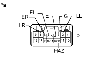
 |
Measure the resistance according to the value(s) in the table below.
- Standard Resistance:
Tester Connection Condition Specified Condition 4 (E) - Body ground Always Below 1 Ω
TURN SIGNAL FLASHER ASSEMBLY > ON-VEHICLE INSPECTION |
| 1. CHECK TURN SIGNAL FLASHER ASSEMBLY |
|
Measure the resistance according to the value(s) in the table below.
| Tester Connection | Condition | Specified Condition |
| 4 (E) - Body ground | Always | Below 1 Ω |
Measure the voltage according to the value(s) in the table below.
| Tester Connection | Condition | Specified Condition |
| 8 (LR) - 4 (E) | Hazard warning switch off | Below 1 V |
| Hazard warning switch on | Alternating between 11 to 14 V and below 1 V (60 to 120 times per minute) | |
| 2 (LL) - 4 (E) | Hazard warning switch off | Below 1 V |
| Hazard warning switch on | Alternating between 11 to 14 V and below 1 V (60 to 120 times per minute) | |
| 1 (B) - 4 (E) | Always | 11 to 14 V |
| 3 (IG) - 4 (E) | Ignition switch ON | 11 to 14 V |
| 6 (EL) - 4 (E) | Ignition switch ON Headlight dimmer switch (turn left) off | 9 V or higher |
| Ignition switch ON Headlight dimmer switch (turn left) on | Below 1 V | |
| 7 (ER) - 4 (E) | Ignition switch ON Headlight dimmer switch (turn right) off | 9 V or higher |
| Ignition switch ON Headlight dimmer switch (turn right) on | Below 1 V | |
| 12 (HAZ) - 4 (E) | Hazard warning switch off | 9 V or higher |
| Hazard warning switch on | Below 1 V |
| *a | Component with harness connected (Stop Light Switch Assembly) |