 |
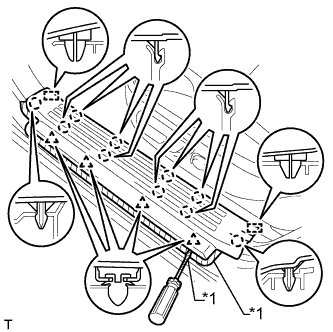
Put protective tape around the door scuff plate assembly LH.
| *1 | Protective Tape |
TURN SIGNAL FLASHER ASSEMBLY > REMOVAL |
| 1. REMOVE DOOR SCUFF PLATE ASSEMBLY LH |
|
Put protective tape around the door scuff plate assembly LH.
| *1 | Protective Tape |
Using a screwdriver, detach the 4 clips, 10 claws and 2 guides to remove the door scuff plate assembly LH.
| 2. REMOVE COWL SIDE TRIM BOARD LH |
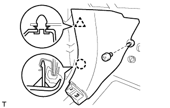 |
Remove the clip.
Detach the clip and claw to remove the cowl side trim board LH.
| 3. REMOVE NO. 2 SWITCH HOLE BASE |
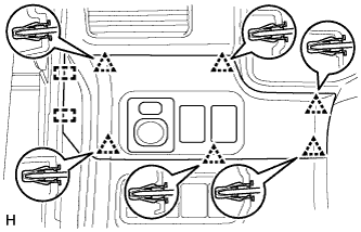 |
Detach the 6 clips and 2 guides.
Disconnect each connector and remove the No. 2 switch hole base.
| 4. REMOVE NO. 1 INSTRUMENT CLUSTER FINISH PANEL GARNISH |
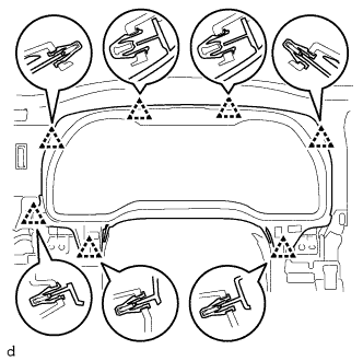 |
Detach the 7 clips to remove the instrument cluster finish panel sub-assembly.
| 5. REMOVE LOWER INSTRUMENT PANEL FINISH PANEL SUB-ASSEMBLY |
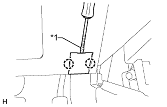 |
Using a screwdriver, detach the 2 claws to open the cover.
| *1 | Protective Tape |
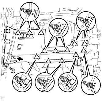 |
Remove the 2 bolts <C>.
Detach the 13 clips and 2 guides.
Disconnect each connector and hood lock control cable assembly and remove the lower instrument panel finish panel sub-assembly.
| 6. REMOVE TURN SIGNAL FLASHER ASSEMBLY |
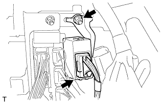 |
Disconnect the connector.
Remove the nut and flasher.