 |
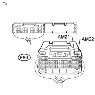
Disconnect the F80 power management control ECU connector.
SMART KEY SYSTEM (for Start Function) > Power Source Mode does not Change to ON (ACC) |
| 1.CHECK HARNESS AND CONNECTOR (BATTERY - POWER MANAGEMENT CONTROL ECU) |
|
Disconnect the F80 power management control ECU connector.
Measure the voltage according to the value(s) in the table below.
| Tester Connection | Condition | Specified Condition |
| F80-2 (AM21) - Body ground | Always | 9.5 to 14 V |
| F80-1 (AM22) - Body ground |
| *a | Rear view of wire harness connector (to Power Management Control ECU) |
|
| ||||
| OK | |
 |
| 2.CHECK HARNESS AND CONNECTOR (POWER MANAGEMENT CONTROL ECU - BODY GROUND) |
Disconnect the F80 power management control ECU connector.
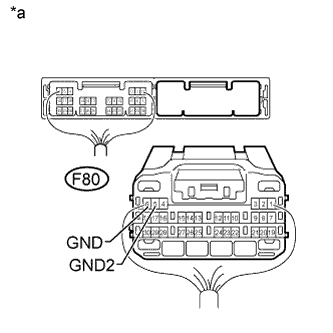 |
Measure the resistance according to the value(s) in the table below.
| Tester Connection | Condition | Specified Condition |
| F80-6 (GND) - Body ground | Always | Below 1 Ω |
| F80-5 (GND2) - Body ground |
| *a | Rear view of wire harness connector (to Power Management Control ECU) |
|
| ||||
| OK | |
|
| 3.INSPECT DRIVER SIDE JUNCTION BLOCK ASSEMBLY (ACC RELAY) |
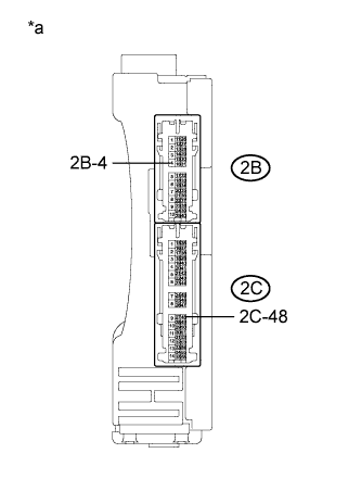 |
Remove the driver side junction block assembly.
Measure the resistance according to the value(s) in the table below.
| Tester Connection | Condition | Specified Condition |
| 2C-48 - 2B-4 | 20°C (68°F) | 101.25 to 123.75 Ω |
| *a | Component without harness connected (Driver Side Junction Block Assembly) |
|
| ||||
| OK | |
|
| 4.CHECK HARNESS AND CONNECTOR (POWER MANAGEMENT CONTROL ECU - DRIVER SIDE JUNCTION BLOCK ASSEMBLY) |
Disconnect the F80 power management control ECU connector.
Disconnect the 2C driver side junction block assembly connector.
Measure the resistance according to the value(s) in the table below.
| Tester Connection | Condition | Specified Condition |
| F80-19 (ACCD) - 2C-48 | Always | Below 1 Ω |
| F80-19 (ACCD) - Body ground | Always | 10 kΩ or higher |
|
| ||||
| OK | |
|
| 5.CHECK HARNESS AND CONNECTOR (DRIVER SIDE JUNCTION BLOCK ASSEMBLY - BODY GROUND) |
Disconnect the 2B driver side junction block assembly connector.
Measure the resistance according to the value(s) in the table below.
| Tester Connection | Condition | Specified Condition |
| 2B-4 - Body ground | Always | Below 1 Ω |
|
| ||||
| OK | |
|
| 6.CHECK POWER MANAGEMENT CONTROL ECU |
Connect the power management control ECU connector.
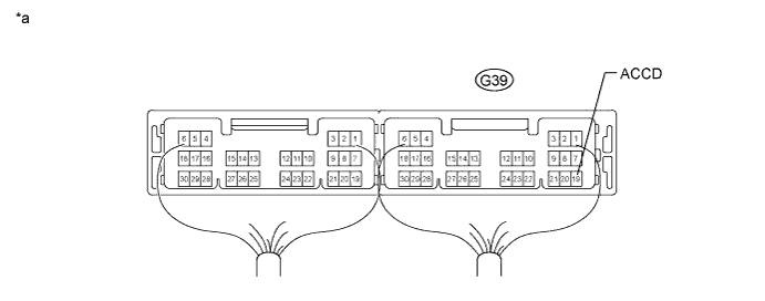
| *a | Component with harness connected (Power Management Control ECU) | - | - |
Measure the voltage according to the value(s) in the table below.
| Tester Connection | Switch Condition | Specified Condition |
| F80-19 (ACCD) - Body ground | Engine switch off | Below 1 V |
| Engine switch on (ACC) | ((Voltage at terminal AM21 or AM22) minus 2.0 V) or higher |
|
| ||||
| OK | |
|
| 7.CONFIRMATION TEST |
Check that the power source mode changes to on (ACC) and on (IG) when operating the engine switch.
|
| ||||
| OK | ||
 | ||
| ||
