 |
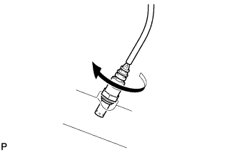
Temporarily install the sensor to the exhaust pipe by hand.
EXHAUST PIPE > INSTALLATION |
| 1. INSTALL HEATED OXYGEN SENSOR (for Bank 1 Sensor 2) |
|
Temporarily install the sensor to the exhaust pipe by hand.
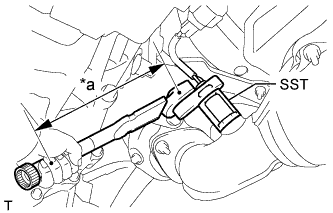 |
Using SST, tighten the sensor.
| *1 | Fulcrum Length |
Connect the sensor connector.
| 2. INSTALL HEATED OXYGEN SENSOR (for Bank 2 Sensor 2) |
|
Temporarily install the sensor to the exhaust pipe by hand.
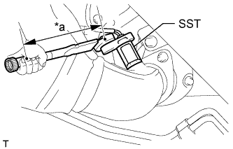 |
Using SST, tighten the sensor.
| *1 | Fulcrum Length |
| 3. INSTALL FRONT NO. 2 EXHAUST PIPE ASSEMBLY |
Install the exhaust pipe support.
Set 2 new gaskets to the front No. 2 exhaust pipe assembly.
Connect the front No. 2 exhaust pipe assembly to the exhaust pipe support and exhaust manifold.
Install 2 new nuts.
Connect the heated oxygen sensor connector.
| 4. INSTALL EXHAUST PIPE STOPPER BRACKET (for 4WD) |
Install the exhaust pipe stopper bracket with the 2 bolts.
| 5. INSTALL FRONT EXHAUST PIPE ASSEMBLY |
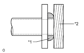 |
Using a plastic-faced hammer and wooden block, tap in a new gasket until its surface is flush with the front exhaust pipe assembly.
| *1 | Gasket |
| *2 | Wooden Block |
Install a new gasket and the front exhaust pipe assembly to the exhaust manifold with 2 new nuts.
Connect the front exhaust pipe assembly to the front No. 2 exhaust pipe assembly with the 2 bolts.
Connect the heated oxygen sensor connector.
| 6. INSTALL CENTER EXHAUST PIPE ASSEMBLY |
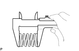 |
Using a vernier caliper, measure the free length of the compression spring.
Set a new gasket to the front exhaust pipe assembly.
Install the 4 exhaust pipe supports.
Connect the center exhaust pipe assembly to the 4 exhaust pipe supports.
Install the center exhaust pipe assembly with the 2 compression springs and 2 bolts.
| 7. INSTALL TAILPIPE ASSEMBLY |
Install the exhaust pipe support.
Set a new gasket to the center exhaust pipe assembly.
Connect the tailpipe to the exhaust pipe support.
Install the 2 bolts.
| 8. INSPECT FOR EXHAUST GAS LEAK |
| 9. INSTALL REAR BUMPER SIDE BRACKET RH (w/o Intuitive Parking Assist System) |
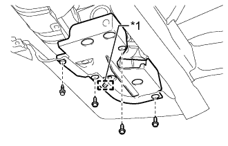 |
Attach the guide and install the rear bumper side bracket RH with the 3 screws and clip.
| *1 | Guide |
| 10. INSTALL REAR BUMPER SIDE BRACKET RH (w/ Intuitive Parking Assist System) |
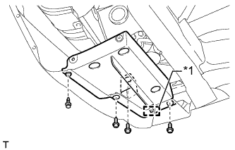 |
Attach the guide and install the rear bumper side bracket RH with the 3 screws and clip.
| *1 | Guide |
| 11. INSTALL REAR QUARTER PANEL MUDGUARD RH (w/o Intuitive Parking Assist System) |
Install the rear quarter panel mudguard RH with the 6 screws and 3 clips.
| 12. INSTALL REAR QUARTER PANEL MUDGUARD RH (w/ Intuitive Parking Assist System) |
Install the rear quarter panel mudguard RH with the 4 screws and 4 clips.
| 13. INSTALL REAR ENGINE UNDER COVER ASSEMBLY |
Install the rear engine under cover assembly with the 4 bolts.
| 14. INSPECT FOR EXHAUST GAS LEAK |