Grip the No. 1 instrument cluster finish panel garnish and pull it diagonally upward toward the rear to detach the 5 clips and remove the No. 1 instrument cluster finish panel garnish.
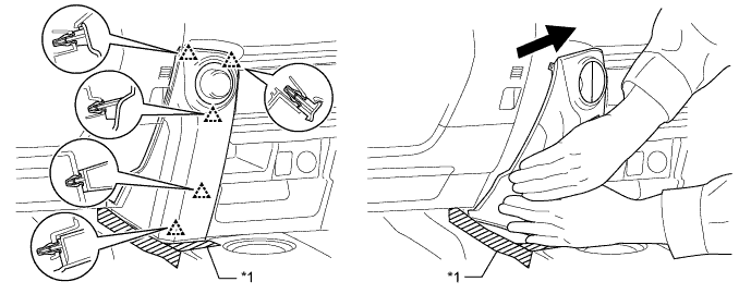
| *1 | Protective Tape | - | - |
CENTER POWER OUTLET SOCKET > REMOVAL |
| 1. REMOVE NO. 1 INSTRUMENT CLUSTER FINISH PANEL GARNISH |
Put protective tape around the No. 1 instrument cluster finish panel garnish.
Grip the No. 1 instrument cluster finish panel garnish and pull it diagonally upward toward the rear to detach the 5 clips and remove the No. 1 instrument cluster finish panel garnish.
| *1 | Protective Tape | - | - |
| 2. REMOVE NO. 2 INSTRUMENT CLUSTER FINISH PANEL GARNISH |
Open the instrument cluster finish panel lid.
Put protective tape around the No. 2 instrument cluster finish panel garnish.
Grip the No. 2 instrument cluster finish panel garnish and pull it diagonally upward toward the rear to detach the 5 clips and remove the No. 2 instrument cluster finish panel garnish.
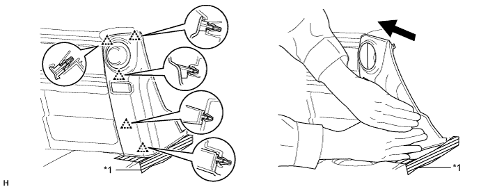
| *1 | Protective Tape | - | - |
| 3. REMOVE FRONT NO. 1 CONSOLE BOX INSERT |
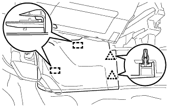 |
Detach the 2 clips and 2 guides to remove the front No. 1 console box insert.
| 4. REMOVE FRONT NO. 2 CONSOLE BOX INSERT |
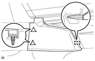 |
Detach the 2 clips and guide to remove the front No. 2 console box insert.
| 5. REMOVE SHIFT LEVER KNOB SUB-ASSEMBLY |
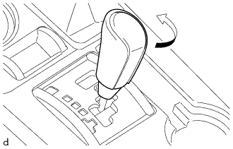 |
Turn the shift lever knob sub-assembly in the direction indicated by the arrow and remove it.
| 6. REMOVE SHIFT LEVER KNOB SUB-ASSEMBLY (for VF2A) |
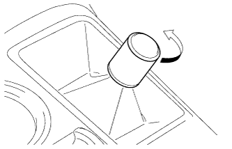 |
Turn the shift lever knob sub-assembly in the direction indicated by the arrow and remove it.
| 7. REMOVE UPPER CONSOLE PANEL SUB-ASSEMBLY |
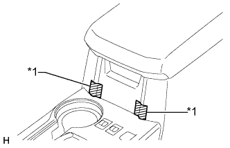 |
Put protective tape around the upper console panel sub-assembly.
| *1 | Protective Tape |
Using a moulding remover, detach the 10 clips.
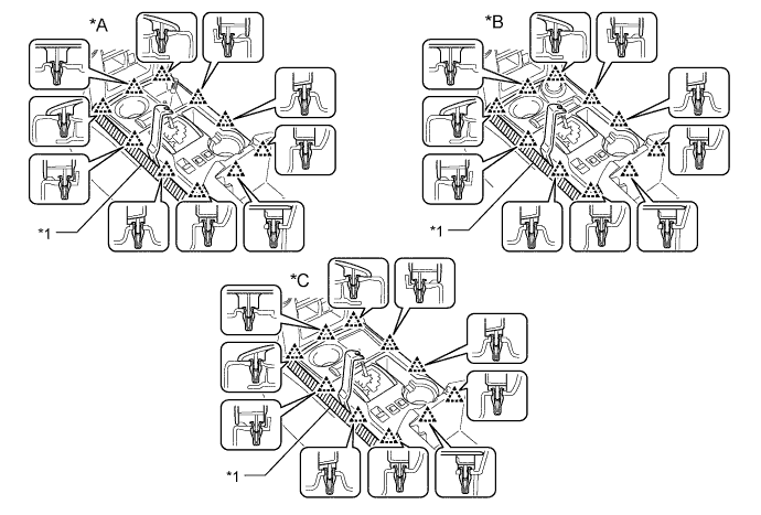
| *A | for VF2A | *B | for VF2BM, VF4BM |
| *C | for 2WD | - | - |
| *1 | Protective Tape | - | - |
Disconnect each connector and remove the upper console panel sub-assembly.
| 8. REMOVE NO. 2 CONSOLE BOX RETAINER |
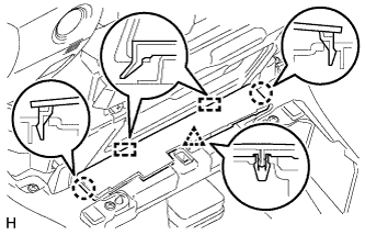 |
Detach the clip, 2 claws and 2 guides to remove the No. 2 console box retainer.
| 9. REMOVE REAR CONSOLE BOX ASSEMBLY |
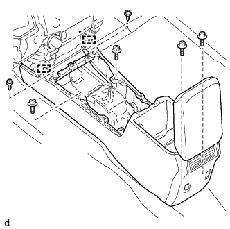 |
Remove the 4 bolts and 2 screws.
Detach the 2 guides.
Disconnect each connector and remove the rear console box assembly.
| 10. REMOVE NO. 1 POWER OUTLET SOCKET ASSEMBLY |
Disconnect the power outlet socket assembly connector.
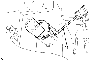 |
Using a screwdriver, detach the claw to remove the No. 1 power outlet socket assembly.
| *1 | Protective Tape |
| 11. REMOVE NO. 1 POWER OUTLET SOCKET COVER |
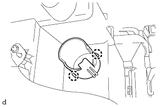 |
Detach the 2 claws to remove the No. 1 power outlet socket cover.
| 12. REMOVE REAR CONSOLE END PANEL |
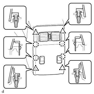 |
Detach the 4 clips and 4 claws to remove the rear console end panel.
Disconnect the 2 power outlet socket assembly connectors.
| 13. REMOVE NO. 3 POWER OUTLET SOCKET ASSEMBLY |
Detach the connector clamp.
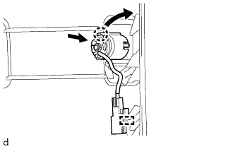 |
While pulling the claw of the No. 3 power outlet socket assembly in the direction of the arrow, push the No. 3 power outlet socket assembly toward the inside of the chamber to remove it.
| 14. REMOVE CENTER POWER OUTLET SOCKET COVER |
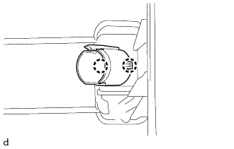 |
Detach the 2 claws to remove the center power outlet socket cover.