FRONT CONSOLE BOX > REASSEMBLY |
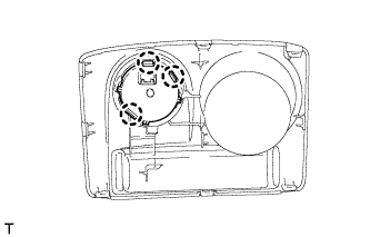
| 1. INSTALL TRANSFER POSITION SWITCH (for VF2BM) |
Attach the 3 claws to install the transfer position switch.
| 2. INSTALL TRANSFER POSITION SWITCH (for VF4BM) |
|
Attach the 3 claws to install the transfer position switch.
| 3. INSTALL NO. 2 BOX BOTTOM MAT (for 2WD) |
Attach the 4 claws to install the No. 2 box bottom mat.
| 4. INSTALL FRONT UPPER CONSOLE PANEL GARNISH |
for VF2A:
Attach the 6 claws to install the front upper console panel garnish.
for 2WD, for VF2BM, VF4BM:
Attach the 10 claws to install the front upper console panel garnish.
| 5. INSTALL SHIFTING HOLE COVER SUB-ASSEMBLY (for VF2A) |
Attach the 6 claws to install the shifting hole cover sub-assembly.
| 6. INSTALL SWITCH BASE |
Install the switch base with the 2 screws.
| 7. INSTALL SEAT HEATER SWITCH (w/ Seat Heater System) |
Attach the 4 claws to install the 2 switches.
Connect the 2 connectors.
| 8. INSTALL BACK DOOR POWER WINDOW REGULATOR SWITCH ASSEMBLY |
Attach the 2 claws to install the regulator switch.
| 9. INSTALL CONSOLE CUP HOLDER BOX |
Install the console cup holder box with the 6 screws.
| 10. INSTALL CONSOLE COMPARTMENT DOOR HINGE SUB-ASSEMBLY |
Install the console compartment door hinge sub-assembly with the 4 screws.
Attach the 6 claws to install the console compartment inner door.
Install the 4 screws.
| 11. INSTALL CONSOLE COMPARTMENT DOOR LOCK SUB-ASSEMBLY |
Install the console compartment door lock sub-assembly with the 2 screws.
| 12. INSTALL CONSOLE COMPARTMENT DOOR SUB-ASSEMBLY |
Install the console compartment door sub-assembly with the 6 screws.
| 13. INSTALL CONSOLE BOX REGISTER ASSEMBLY |
Attach the 4 claws to install the console box register assembly.
| 14. INSTALL CENTER POWER OUTLET SOCKET COVER |
Attach the 2 claws to install the center power outlet socket cover.
| 15. INSTALL NO. 3 POWER OUTLET SOCKET ASSEMBLY |
Attach the claw to install the No. 3 power outlet socket assembly.
Attach the connector clamp.
| 16. INSTALL REAR CONSOLE END PANEL |
Connect the 2 power outlet socket assembly connectors.
Attach the 4 clips and 4 claws to install the rear console end panel.
| 17. INSTALL NO. 1 POWER OUTLET SOCKET COVER |
Attach the 2 claws to install the No. 1 power outlet socket cover.
| 18. INSTALL NO. 1 POWER OUTLET SOCKET ASSEMBLY |
Attach the claw to install the No. 1 power outlet socket assembly.
Connect the No. 1 power outlet socket assembly connector.