Air Cleaner Assembly
An air cleaner element with an full fabric is used.
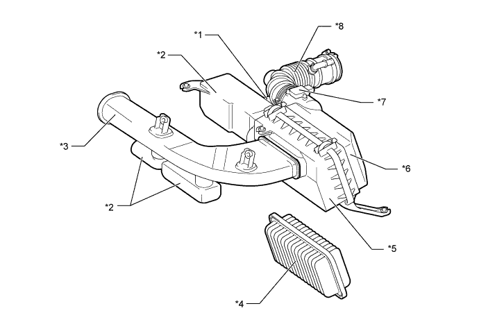
Text in Illustration *1 Intake Air Resonator *2 Resonator *3 Air Cleaner Inlet Assembly *4 Air Cleaner Filter Element Sub-assembly *5 Air Cleaner Cap Sub-assembly *6 Air Cleaner Case Sub-assembly *7 Intake Mass Air Flow Meter Sub-assembly *8 No.1 Air Cleaner Hose
Chamber Assembly
A new mechanism has been developed which utilizes the air vibrations present in the intake system and, linked with the driver's operation of the accelerator pedal, draws the air intake sound directly into the vehicle cabin.
Modulation of the air intake sound for city driving and sports driving is carried out so that during slow acceleration, consideration has been made with the air intake sound to avoid feelings of stress from city driving, and during full-throttle acceleration, a sports car-like air intake sound is produced.
The damper inside the chamber assembly resonates to provide the optimal air intake sound.
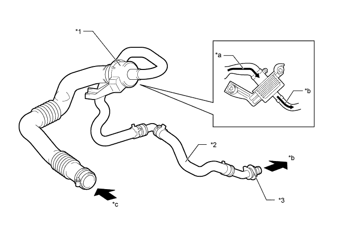
Text in Illustration *1 Damper Section *2 Hose *3 Connector - - *a Air Vibrations *b to Vehicle Cabin *c from No.1 Air Cleaner Hose - -
Throttle Body
A linkless-type throttle body in which the throttle position sensor and the throttle control motor are integrated is used. It achieves excellent throttle valve control.
The throttle valve driving motor uses a DC motor with excellent response and minimal power consumption. Driver operations (the extent to which the accelerator pedal is pressed) is sent to the ECM by an accelerator position sensor located on the accelerator pedal. The ECM determines how wide to open the throttle according to the driving state, and activates the electronic throttle motor. The aperture of the throttle valve is fed back into the ECM by the throttle position sensor.
The dual nature of the system (main and sub), containing both accelerator position sensor and throttle position sensor, constantly monitors the system for errors.
If an error is detected, the driver is informed via a warning light located on the meter, and power to the motor is cut off. The throttle valve aperture returns to its predetermined state by means of a throttle valve return spring. It is possible to regulate the engine output in accordance with the aperture of the accelerator by cutting off fuel injection and delaying ignition.
A large-bore throttle has been adopted to accommodate high output.
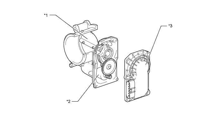
Text in Illustration *1 Throttle Valve *2 Throttle Control Motor (DC Motor) *3 Throttle Position Sensor - -
Intake Manifold
A lightweight plastic is used for the intake manifold.
With the adoption of the D-4S system, fuel injector assembly installation holes for port injection have been added on the intake manifold side area.
Port diameter has been optimized in order to improve engine output.
The engine's center of gravity has been lowered by adopting an intake manifold with a low overall height, and engine response has been improved by shortening the length of the port.
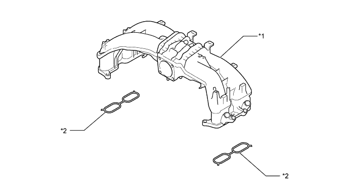
Text in Illustration *1 Intake Manifold *2 No.1 Intake Manifold To Head Gasket