 |
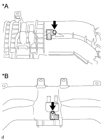
Remove the bolt and manifold absolute pressure sensor from the intake manifold.
| *A | for Resin Intake Manifold |
| *B | for Aluminum Intake Manifold |
INTAKE MANIFOLD > DISASSEMBLY |
| 1. REMOVE MANIFOLD ABSOLUTE PRESSURE SENSOR |
|
Remove the bolt and manifold absolute pressure sensor from the intake manifold.
| *A | for Resin Intake Manifold |
| *B | for Aluminum Intake Manifold |
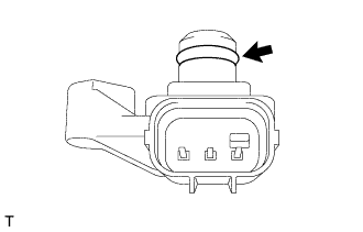 |
Remove the O-ring from the manifold absolute pressure sensor.
| 2. REMOVE PURGE VALVE |
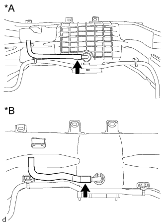 |
Disconnect the No. 1 fuel vapor feed hose from the intake manifold.
| *A | for Resin Intake Manifold |
| *B | for Aluminum Intake Manifold |
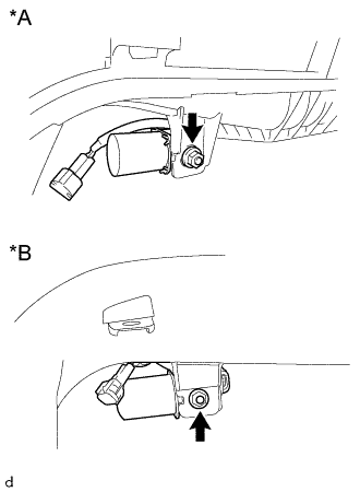 |
Remove the nut and purge valve.
| *A | for Resin Intake Manifold |
| *B | for Aluminum Intake Manifold |
| 3. REMOVE CAP (for Automatic Transmission) |
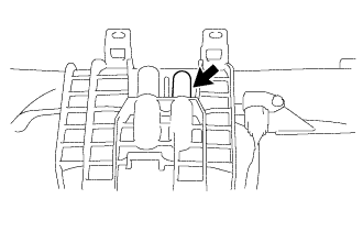 |
Remove the cap from the intake manifold.
| 4. REMOVE FUEL DELIVERY PIPE (for Bank 2) |
Disconnect the No. 2 fuel delivery pipe sub-assembly from the fuel delivery pipe.
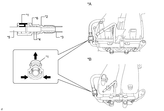
| *A | for Resin Intake Manifold | *B | for Aluminum Intake Manifold |
| *1 | Retainer | *2 | No. 2 Fuel Delivery Pipe Sub-assembly Connector |
| *3 | Nylon Tube | *4 | O-ring |
| *5 | fuel delivery pipe | *6 | Top Hat |
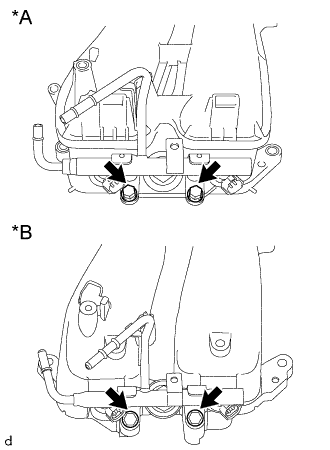 |
Remove the 2 bolts and the fuel delivery pipe from the intake manifold.
| *A | for Resin Intake Manifold |
| *B | for Aluminum Intake Manifold |
Remove the 2 O-rings.
| 5. REMOVE FUEL DELIVERY PIPE (for Bank 1) |
| 6. REMOVE NO. 2 FUEL DELIVERY PIPE SUB-ASSEMBLY |
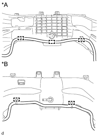 |
Disengage the 3 clamps and remove the No. 2 fuel delivery pipe sub-assembly from the intake manifold. (for resin intake manifold)
Disengage the 2 clamps and remove the No. 2 fuel delivery pipe sub-assembly from the intake manifold. (for aluminum intake manifold)
| *A | for Resin Intake Manifold |
| *B | for Aluminum Intake Manifold |