 |
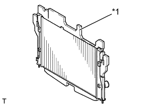
Install the new radiator packing.
| *1 | Radiator Packing |
- HINT:
- Cut the radiator packing at the same position in the removal.
RADIATOR > INSTALLATION |
| 1. INSTALL RADIATOR PACKING (LOWER) |
Install the new radiator packing.
| 2. INSTALL NO. 2 RADIATOR PACKING |
Install the new No. 2 radiator packing.
| 3. INSTALL NO. 1 RADIATOR PACKING |
Install the new No. 1 radiator packing.
| 4. INSTALL RADIATOR PACKING (UPPER) |
|
Install the new radiator packing.
| *1 | Radiator Packing |
| 5. INSTALL OUTLET RADIATOR HOSE |
Since the radiator hose must be attached in the correct position, apply match marks before removing it.
Install the outlet radiator hose to the radiator assembly and secure it with the clamp.
| 6. INSTALL NO. 1 RADIATOR HOSE |
Since the radiator hose must be attached in the correct position, apply match marks before removing it.
Install the No. 1 radiator hose to the water filler sub-assembly and secure it with the clamp.
| 7. INSTALL INLET RADIATOR HOSE |
Since the radiator hose must be attached in the correct position, apply match marks before removing it.
Install the inlet radiator hose to the radiator assembly and secure it with the clamp.
| 8. INSTALL RADIATOR ASSEMBLY |
Install the 2 radiator support cushions to the radiator assembly.
While lifting the outlet radiator hose, install the radiator assembly.
Attach the claw and install the thermistor assembly.
Install the radiator support RH with the 2 bolts.
Install the radiator support LH with the 2 bolts.
| 9. INSTALL FAN SHROUD |
Engage the fitting sections in the bottom of the fan shroud with the fitting sections of the radiator assembly.
Attach the 2 claws and install the fan shroud to the radiator assembly.
Connect the 2 cooling fan motor connectors and 2 clamps to the radiator assembly.
| 10. INSTALL COOLER CONDENSER ASSEMBLY |
Install the cooler condenser assembly to the radiator assembly with the 5 bolts.
| 11. INSTALL RADIATOR SUPPORT SUB-ASSEMBLY |
Install the 6 bolts and radiator support sub-assembly.
| 12. INSTALL HOOD LOCK ASSEMBLY (for LHD) |
Apply MP grease to the sliding areas of the hood lock assembly.
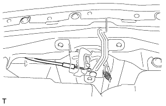 |
Connect the hood lock control cable assembly to the hood lock assembly.
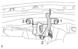 |
Install the hood lock assembly with the 3 bolts in the order shown in the illustration.
| 13. INSTALL HOOD LOCK ASSEMBLY (for RHD) |
Apply MP grease to the sliding areas of the hood lock assembly.
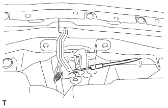 |
Connect the hood lock control cable assembly to the hood lock assembly.
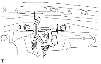 |
Install the hood lock assembly with the 3 bolts in the order shown in the illustration.
| 14. INSTALL WATER FILLER SUB-ASSEMBLY |
Install the water filler sub-assembly and water filler bracket with the 4 bolts.
Connect the inlet radiator hose and No. 1 radiator hose to the radiator assembly with the 2 clamps.
Connect the radiator cap hose to the water filler sub-assembly.
| 15. INSTALL RADIATOR COVER PLATE |
Install the radiator cover plate with the 6 clips.
| 16. INSTALL AIR CLEANER DUCT |
Install the air cleaner duct with the 2 bolts.
| 17. INSTALL RADIATOR RESERVE TANK ASSEMBLY |
Install the radiator reserve tank assembly with the 2 bolts.
| 18. CONNECT OUTLET RADIATOR HOSE |
Since the radiator hose must be attached in the correct position, apply match marks before removing it.
Connect the outlet radiator hose to the water outlet with the hose clamp.
| 19. ADD ENGINE COOLANT |
Tighten the radiator drain cock plug.
Pour in coolant of the specified density until it reaches the base of the entrance to the water inlet.
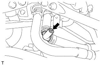 |
Open the air bleed plug on the heater hose side. (for LHD)
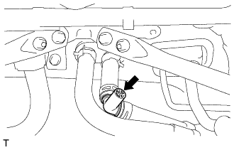 |
Open the air bleed plug on the heater hose side. (for RHD)
If the water level in the entrance to the water inlet drops, pour coolant in until it reaches the base of the entrance to the water inlet.
Close the air bleed plug when the coolant begins to come out of the air bleed valve on the heater hose side.
Pour in coolant of the specified concentration until it reaches the "FULL" level of the radiator reserve tank.
Close the radiator cap. [*1]
Start the engine, race it 5 to 6 times at under 3000 rpm or less, and then stop the engine. [*2]
1 minute after stopping the engine, remove the radiator cap and pour coolant in if the water level in the entrance to the water inlet has dropped. [*3]
Repeat operations [*1], [*2], and [*3] until the water level in the entrance to the water inlet does not drop.
Close the radiator cap and the radiator reserve tank cap.
Start the engine, set the heater on full warm, and then run it with the blower speed set to "LO".
Run the engine at 2000 rpm or less until the radiator fan starts and stops. [*4]
Stop the engine and wait until the coolant temperature drops to 30 °C (86 °F) or less. [*5]
Remove the radiator cap and, if the volume of coolant has dropped, pour coolant in until it reaches the base of the entrance to the water inlet and until it reaches the "FULL" level in the radiator reserve tank. [*6]
Close the radiator cap. [*7]
Set the heater to full warm, and, with the blower speed set to "LO", race the engine at 3000 rpm or less. [*8]
At this point, if the engine coolant can be heard flowing in the heater core, repeat operations [*4], [*5], [*6], [*7], and [*8].
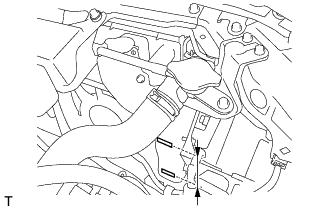 |
When the water level no longer drops, adjust the water level so that the water level in the radiator reserve tank reaches the "FULL" line.
| 20. INSPECT FOR COOLANT LEAK |
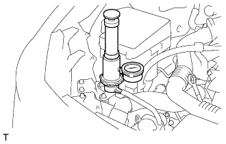 |
Fill the radiator with coolant and attach a radiator cap tester.
Warm up the engine.
Using a radiator cap tester, increase the pressure inside the radiator to 137 kPa (1.4 kgf/cm2, 20 psi), and check that the pressure does not drop.
If the pressure drops, check the hoses, radiator and water pump for leaks. If no external leaks are found, check the heater core, cylinder block and cylinder head.
| 21. INSTALL NO. 1 ENGINE UNDER COVER |
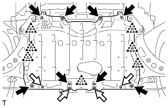 |
Install the No. 1 engine under cover with the 12 bolts and engage the 7 clips.
 | Bolt A |
 | Bolt B |
| 22. INSTALL FRONT BUMPER COVER |
| 23. INSTALL AIR CLEANER CASE SUB-ASSEMBLY |
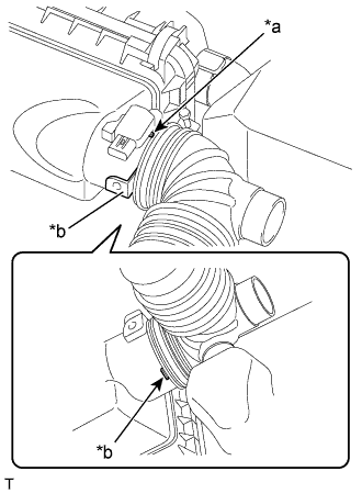 |
Connect the hose.
| *a | match marks |
| *b | Stopper |