 |
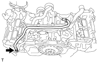
Connect the No. 2 water by-pass hose with the clamp.
ENGINE UNIT > INSTALLATION |
| 1. INSTALL IGNITION COIL ASSEMBLY |
Install the 4 ignition coils with the 4 bolts.
| 2. INSTALL NO. 1 WATER BY-PASS PIPE (for Manual Transmission) |
Install the No. 1 water by-pass pipe with the 2 bolts.
Connect the water by-pass hose with the hose clamp.
| 3. INSTALL NO. 1 WATER BY-PASS PIPE (for Automatic Transmission) |
Install the No. 1 water by-pass pipe with the 2 bolts.
Connect the 2 water by-pass hoses with the 2 hose clamps.
| 4. CONNECT NO. 3 TRANSMISSION OIL COOLER HOSE (for Automatic Transmission) |
Connect the No. 3 transmission oil cooler hose with the hose clamp.
| 5. INSTALL NO. 2 WATER BY-PASS HOSE |
|
Connect the No. 2 water by-pass hose with the clamp.
| 6. CONNECT NO. 2 VENTILATION HOSE |
Connect the No. 2 ventilation hose.
| 7. INSTALL ENGINE WIRE |
Connect the ground wire with the 2 bolts.
Connect each connector and each clamp to fix the engine wire as shown in the illustration, and check that the engine wire is correctly installed.
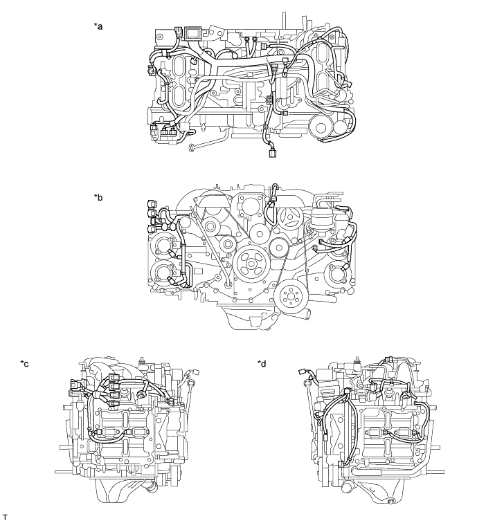
| *a | Upper side | *b | Front side |
| *c | Right side | *d | Left side |
| 8. INSTALL PUMP DRIVE CASE ASSEMBLY |
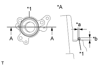 |
Using a sealer gun, apply seal packing in a continuous line as shown in the illustration.
| *A | A-A cross-section |
| *1 | Seal Packing |
| *a | Seal Application Position : Within 1 mm (0.039 in.) from Edge |
| *b | Seal Diameter : 2 to 4 mm (0.079 to 0.158 in.) |
Using a 6 mm hexagon wrench, install the pump drive case assembly with the 3 bolts.
| 9. INSTALL VALVE LIFTER |
Turn the crankshaft until the flat of the cam is facing the cylinder head cover's fuel pump attachment hole.
Apply a coat of engine oil to the pump activation cam and pump lifter part.
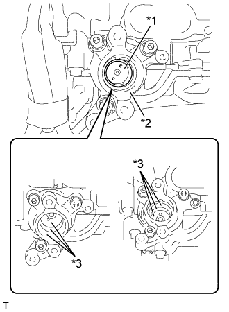 |
Apply new engine oil to the inside of the pump drive case assembly and the underside of the valve lifter, and install the valve lifter to the pump drive case assembly.
| *1 | Valve Lifter |
| *2 | Pump Drive Case Assembly |
| *3 | Location for applying new engine oil |
| 10. INSTALL FUEL PUMP ASSEMBLY |
Apply a light coat of engine oil to a new O-ring and install it to the fuel pump assembly.
Using a "TORX" Plus Socket Wrench, install the fuel pump assembly with the 2 bolts.
| 11. INSTALL FUEL INJECTOR O-RING |
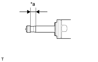 |
Apply engine conditioner to the injector area shown in the illustration. Using a piece of cloth, remove the carbon deposits from the injector and its grooves.
| *a | Clean Area |
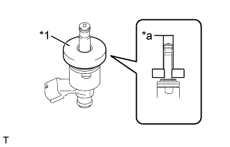 |
Apply engine oil to the injector contact surface of SST (guide). Then attach SST (guide) to the injector with the tapered inner portion facing the tip of the injector, as shown in the illustration.
| *1 | SST (Guide) |
| *a | Tapered Inner Portion |
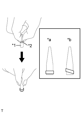 |
Install a new injector seal to SST (holder).
| *1 | SST (holder) |
| *2 | Injector Seal |
| *a | CORRECT |
| *b | INCORRECT |
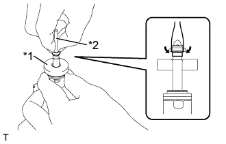 |
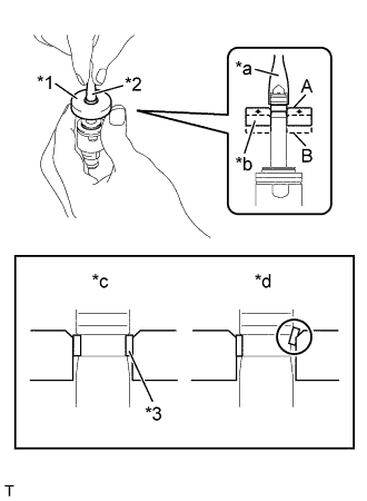
Install SST (holder with injector seal) to the tip of the injector. Slide the seal downward into the injector groove (injector connector side) with your fingers, as shown in the illustration.
| *1 | SST (Guide) |
| *2 | SST (Holder) |
 |
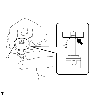
Using SST (holder), gently press downward on the injector seal (injector connector side). Then slowly slide SST (guide) toward the injector tip to settle the seal into the injector groove.
| *1 | SST (Guide) |
| *2 | SST (Holder) |
| *3 | Injector Seal |
| *a | Gently Press |
| *b | Slowly Slide |
| *c | CORRECT |
| *d | INCORRECT |
 |
Slowly slide SST (guide) toward the tip of the injector. When the injector contact surface of SST (guide) aligns with the seal (injector connector side) as shown in the illustration, hold the position for 5 seconds or more to fully align the seal into the injector groove.
| *1 | SST (Guide) |
| *2 | Injector Seal |
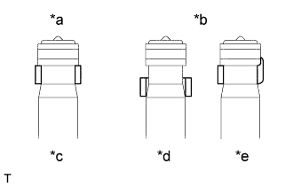 |
After installing the seals, check that they are not scratched, deformed or protruding from the injector groove.
| *a | CORRECT |
| *b | INCORRECT |
| *c | Normal |
| *d | Protruding |
| *e | Deformed |
| 12. INSTALL FUEL INJECTOR ASSEMBLY |
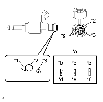 |
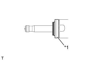
Install new fuel injector backup rings (No. 1 and No. 2) and a new fuel injector seal to the fuel injector assembly as shown in the illustration.
| *1 | No. 1 Fuel Injector Backup Ring |
| *2 | Fuel Injector Seal |
| *3 | No. 2 Fuel Injector Backup Ring |
| *a | Alignment Opening |
| *b | INCORRECT |
| *c | CORRECT |
| *d | Overlapped |
| *e | Normal |
| *f | Stretched |
| *g | Grooved Section |
 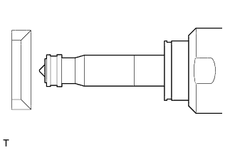 |
Install a new fuel injector insulator to the fuel injector.
| *1 | Fuel Injector Insulator |
Install the No. 1 injector holder.
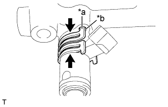  |
Apply new engine oil to the surface of the injector insertion hole in the fuel delivery pipe.
| *a | Protruding section |
| *b | Baffle hole |
 | No gap |
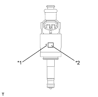
| *1 | Number |
| *2 | Quick Response Code |
Install the No. 1 injector holder while aligning the protrusion on the No. 1 injector holder with the baffle hole on the fuel delivery pipe.
| 13. INSTALL FUEL DELIVERY PIPE LH |
Install the fuel delivery pipe LH with the 2 bolts.
Connect the 2 fuel injector assembly connectors.
| 14. INSTALL FUEL DELIVERY PIPE RH |
Install the fuel delivery pipe RH with the 2 bolts.
Connect the fuel pressure sensor connector and 2 fuel injector assembly connectors.
| 15. INSTALL FUEL DELIVERY PIPE |
Temporarily install the new fuel delivery pipe with the 2 union nuts and 3 bolts.
Tighten the 3 bolts.
Using a union nut wrench, tighten the 2 union nuts.
| 16. INSTALL NO. 2 FUEL DELIVERY PIPE |
Temporarily install the new No. 2 fuel pipe with the 2 union nuts.
Using a union nut wrench, tighten the 2 union nuts.
| 17. INSTALL INTAKE MANIFOLD |
Install 2 new gaskets to the intake manifold.
Install the intake manifold with the 6 bolts.
Engage the 2 clamps and connect the 4 connectors.
Connect the fuel pump connector.
Connect the No. 1 vacuum switching valve assembly connector.
Connect the vacuum sensor connector.
Connect the 2 water by-pass hoses to the throttle body assembly.
Connect the throttle body assembly connector.
| 18. CONNECT VENTILATION HOSE |
Connect the ventilation hose.
| 19. INSTALL FUEL DELIVERY PIPE SUB-ASSEMBLY |
Install the fuel delivery pipe sub-assembly to the fuel pump assembly with a new gasket and the union bolt.
Connect the No. 2 fuel vapor feed hose.
Install the bolt and connect the fuel delivery pipe sub-assembly.
| 20. INSTALL INJECTOR COVER (for Bank 2) |
for Resin Intake Manifold:
Install the injector cover to the intake manifold with the 2 bolts.
for Aluminum Intake Manifold:
Engage the 2 guides and install the injector cover to the intake manifold with the 2 bolts.
| 21. INSTALL INJECTOR COVER (for Bank 1) |
for Resin Intake Manifold:
Install the injector cover to the intake manifold with the 2 bolts.
for Aluminum Intake Manifold:
Engage the 2 guides and install the injector cover to the intake manifold with the 2 bolts.
| 22. INSTALL COMPRESSOR WITH MAGNET CLUTCH |
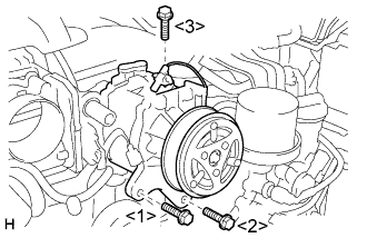 |
Install the compressor with magnet clutch with the 3 bolts.
Connect the connector.
| 23. INSTALL V-RIBBED BELT TENSIONER ASSEMBLY |
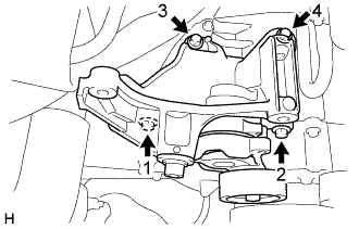 |
Temporarily install the V-ribbed belt tensioner with the 5 bolts.
Tighten the 4 bolts in the order shown in the illustration.
| 24. INSTALL NO. 2 IDLER PULLEY SUB-ASSEMBLY |
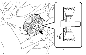 |
Install the washer plate to the No. 2 idler pulley sub-assembly as shown in the illustration.
| *a | Protrusion |
Install the washer plate and No. 2 idler pulley sub-assembly with the bolt.
| 25. INSTALL OIL LEVEL DIPSTICK GUIDE |
Install a new O-ring to the oil level dipstick guide.
Apply a light coat of engine oil to the O-ring.
Install the oil level dipstick guide with the bolt.
Install the oil level dipstick sub-assembly.
| 26. INSTALL GENERATOR ASSEMBLY |
Install the generator assembly with the 2 bolts.
| 27. INSTALL FAN AND GENERATOR V BELT |
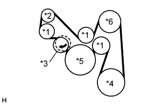 |
Set the fan and generator V belt onto every part.
| *1 | Idler |
| *2 | Generator |
| *3 | Tensioner |
| *4 | Water Pump |
| *5 | Crankshaft |
| *6 | A/C Compressor (w/ Air Conditioning System) |
| Idler Pulley Bracket (w/o Air Conditioning System) |
While turning the belt tensioner clockwise, remove the 3 mm (0.118 in.) hexagon wrench.
Check that the fan and generator V belt fits properly in the ribbed grooves.
| 28. INSTALL BELT GENERATOR COVER |
Install the belt generator cover with the 2 blots.
Engage the 2 wire harness clamps and install the wire harness to the belt generator cover.
| 29. INSTALL GENERATOR COVER |
Install the generator cover with the 2 blots.