 |
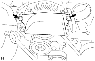
Remove the 2 bolts and generator cover.
ENGINE UNIT > REMOVAL |
| 1. REMOVE ENGINE HANGERS |
Remove the bolt and engine hanger.
| 2. REMOVE GENERATOR COVER |
|
Remove the 2 bolts and generator cover.
| 3. REMOVE BELT GENERATOR COVER |
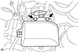 |
Disengage the 2 clamps and separate the wire harness from the belt generator cover.
Remove the 2 bolts and belt generator cover.
| 4. REMOVE FAN AND GENERATOR V BELT |
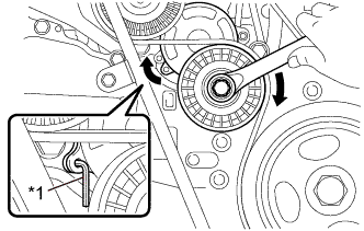 |
While turning the belt tensioner clockwise, align the holes and insert a 3 mm (0.118 in.) hexagon wrench into the holes to hold the belt tensioner.
| *1 | Hexagon Wrench |
Remove the fan and generator V belt from the belt tensioner.
| 5. REMOVE GENERATOR ASSEMBLY |
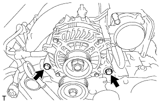 |
Remove the 2 bolts and generator assembly.
| 6. REMOVE OIL LEVEL DIPSTICK GUIDE |
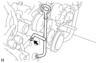 |
Remove the oil level dipstick sub-assembly.
Remove the bolt and oil level dipstick guide.
Remove the O-ring from the oil level dipstick guide.
| 7. REMOVE NO. 2 IDLER PULLEY SUB-ASSEMBLY |
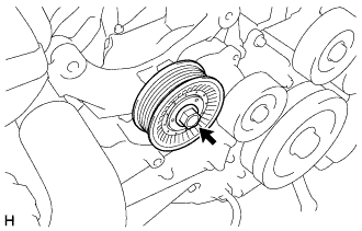 |
Remove the bolt, washer plate and No. 2 idler pulley sub-assembly.
| 8. REMOVE V-RIBBED BELT TENSIONER ASSEMBLY |
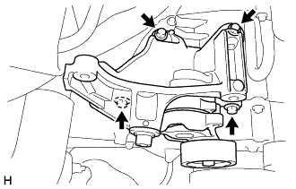 |
Remove the 4 bolts and V-ribbed belt tensioner assembly.
| 9. REMOVE COMPRESSOR WITH MAGNET CLUTCH (w/ Air Conditioning System) |
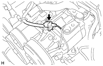 |
Disconnect the connector.
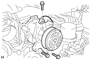 |
Remove the 3 bolts and the compressor with magnet clutch.
| 10. REMOVE IDLER PULLEY BRACKET (w/o Air Conditioning System) |
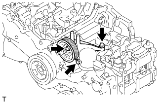 |
Remove the 3 bolts and the idler pulley bracket.
| 11. REMOVE INJECTOR COVER (for Bank 2) |
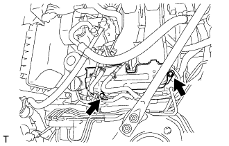 |
Remove the 2 bolts and injector cover.
| 12. REMOVE INJECTOR COVER (for Bank 1) |
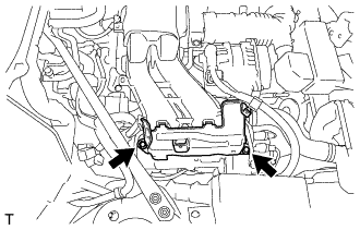 |
Remove the 2 bolts and injector cover.
| 13. REMOVE FUEL DELIVERY PIPE SUB-ASSEMBLY |
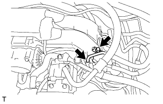 |
Remove the bolt and disconnect the fuel delivery pipe sub-assembly.
Disconnect the No. 2 fuel vapor feed hose.
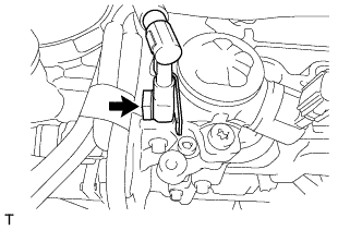 |
Remove the union bolt and gasket, and disconnect the fuel delivery pipe sub-assembly.
| 14. SEPARATE VENTILATION HOSE |
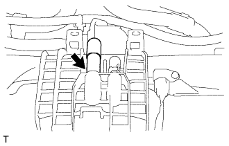 |
Disconnect the ventilation hose.
| 15. REMOVE INTAKE MANIFOLD |
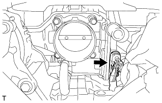 |
Disconnect the throttle body assembly connector.
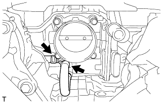 |
Disconnect the 2 water by-pass hoses from the throttle body assembly.
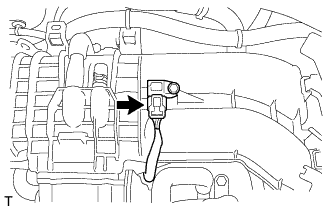 |
Disconnect the vacuum sensor connector.
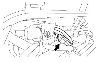 |
Disconnect the No. 1 vacuum switching valve assembly connector.
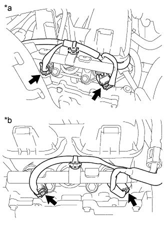 |
Disengage the 2 clamps and disconnect the 4 connectors.
| *a | for Bank 2 |
| *b | for Bank 1 |
Disconnect the wire harness.
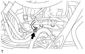 |
Disconnect the fuel pump connector.
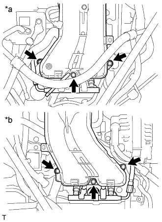 |
Remove the 6 bolts, intake manifold and 2 gaskets.
| *a | for Bank 2 |
| *b | for Bank 1 |
| 16. REMOVE NO. 2 FUEL DELIVERY PIPE |
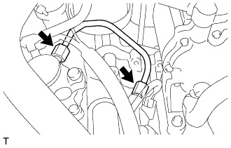 |
Using a union nut wrench, loosen the 2 union nuts and remove the No. 2 fuel delivery pipe.
| 17. REMOVE FUEL DELIVERY PIPE |
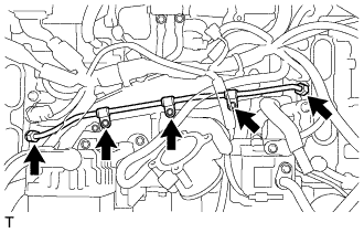 |
Remove the 3 bolts.
Using a union nut wrench, loosen the 2 union nuts and remove the fuel delivery pipe.
| 18. REMOVE FUEL DELIVERY PIPE LH |
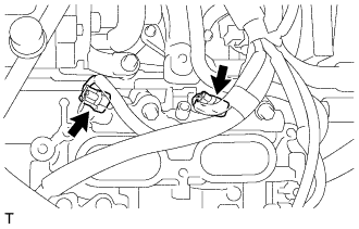 |
Disconnect the 2 fuel injector assembly connectors.
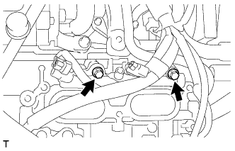 |
Remove the 2 bolts and fuel delivery pipe LH.
| 19. REMOVE FUEL DELIVERY PIPE RH |
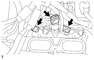 |
Disconnect the fuel pressure sensor connector and 2 fuel injector assembly connectors.
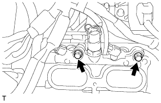 |
Remove the 2 bolts and fuel delivery pipe RH.
| 20. REMOVE FUEL INJECTOR ASSEMBLY |
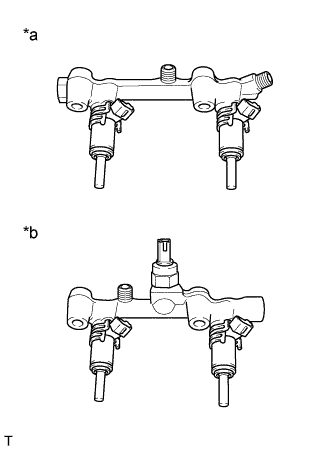 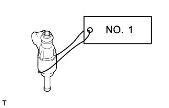 |
Remove the 4 fuel injector assemblies from the fuel delivery pipe.
| *a | for Bank 2 |
| *b | for Bank 1 |
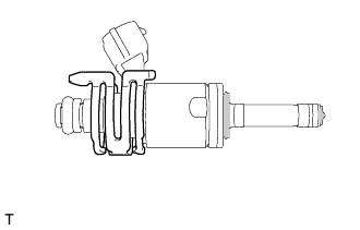 |
Remove the No. 1 injector holders from the fuel injectors.
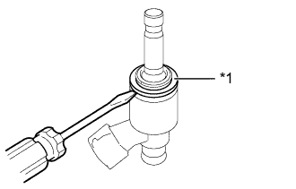 |
Using a screwdriver, remove the fuel injector insulator.
| *1 | Fuel Injector Insulator |
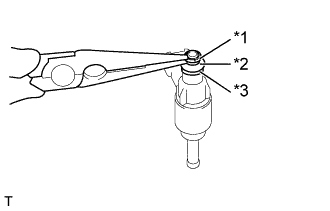 |
Using a needle nose plier, remove the No. 2 fuel injector backup ring.
| *1 | No. 2 Fuel Injector Backup Ring |
| *2 | Fuel Injector Seal |
| *3 | No. 1 Fuel Injector Backup Ring |
Remove the fuel injector seal and No. 1 fuel injector backup ring.
| 21. REMOVE FUEL INJECTOR O-RING |
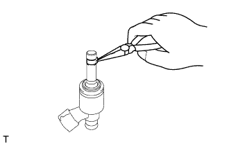 |
Using the tips of a pair of needle nose pliers, pinch and pull one of the fuel injector O-ring at several points to stretch it. Repeat this for the other fuel injector O-ring.
Remove the fuel injector O-ring from the injector.
| 22. REMOVE FUEL PUMP ASSEMBLY |
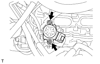 |
Using a "TORX" Plus Socket Wrench, remove the 2 bolts and fuel pump assembly.
Remove the O-ring from the fuel pump assembly.
| 23. REMOVE VALVE LIFTER |
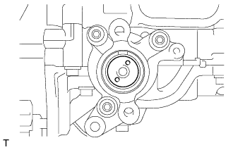 |
Remove the valve lifter from the pump drive case assembly.
| 24. REMOVE PUMP DRIVE CASE ASSEMBLY |
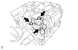 |
Using a 6 mm hexagon wrench, remove the 3 bolts and pump drive case assembly.
| 25. REMOVE ENGINE WIRE |
Remove the 2 bolts and separate the ground wire harness.
Disconnect each connector and clamp, and remove the engine wire.
| 26. REMOVE NO. 2 VENTILATION HOSE |
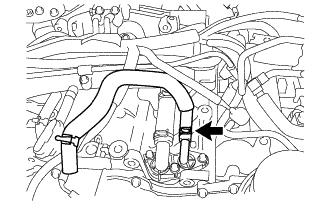 |
Disconnect the No. 2 ventilation hose.
| 27. REMOVE NO. 2 WATER BY-PASS HOSE |
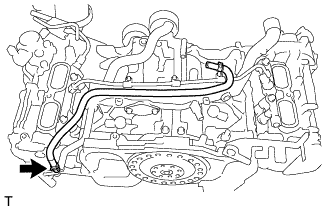 |
Disconnect the No. 2 water by-pass hose.
| 28. REMOVE NO. 3 TRANSMISSION OIL COOLER HOSE (for Automatic Transmission) |
Disconnect the No. 3 transmission oil cooler hose.
| 29. REMOVE NO. 1 WATER BY-PASS PIPE (for Manual Transmission) |
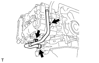 |
Loosen the hose clip and disconnect the water by-pass hose.
Remove the 2 bolts and the No. 1 water by-pass pipe.
| 30. REMOVE NO. 1 WATER BY-PASS PIPE (for Automatic Transmission) |
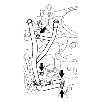 |
Loosen the 2 hose clips and disconnect the 2 water by-pass hoses.
Remove the 2 bolts and No. 1 water by-pass pipe.
| 31. REMOVE IGNITION COIL ASSEMBLY |
Remove the 4 bolts and 4 ignition coil assemblies.