 |
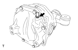
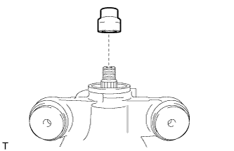
Remove the rear differential breather plug from the rear differential carrier cover.
REAR DIFFERENTIAL CARRIER ASSEMBLY > DISASSEMBLY |
| 1. REMOVE REAR DIFFERENTIAL BREATHER PLUG |
|
Remove the rear differential breather plug from the rear differential carrier cover.
| 2. REMOVE REAR DIFFERENTIAL CARRIER COVER |
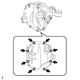 |
Remove the 8 bolts.
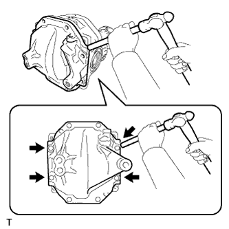 |
Using a brass bar and a hammer, remove the rear differential carrier cover from the rear differential carrier assembly.
| 3. REMOVE REAR DIFFERENTIAL BREATHER PLUG OIL DEFLECTOR |
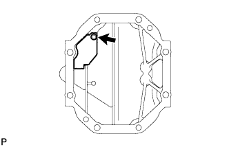 |
Remove the bolt and the rear differential breather plug oil deflector from the rear differential carrier cover.
| 4. SECURE REAR DIFFERENTIAL CARRIER SUB-ASSEMBLY |
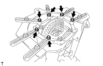 |
Secure the rear differential carrier sub-assembly to the overhaul stand with the 6 bolts.
| 5. INSPECT RUNOUT OF DIFFERENTIAL RING GEAR |
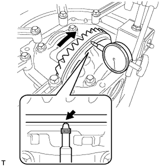 |
Set a dial indicator perpendicular to the end of the differential ring gear face.
Rotate the differential ring gear and measure the runout.
| 6. INSPECT DIFFERENTIAL RING GEAR BACKLASH |
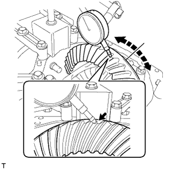 |
While holding the rear drive pinion companion flange sub-assembly, rotate the differential ring gear and measure the backlash.
| 7. INSPECT TOOTH CONTACT BETWEEN RING GEAR AND DRIVE PINION |
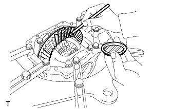 |
Coat 3 or 4 teeth at 3 different positions on the differential ring gear with Prussian blue.
Rotate the differential ring gear in both directions.
Inspect the tooth contact pattern.
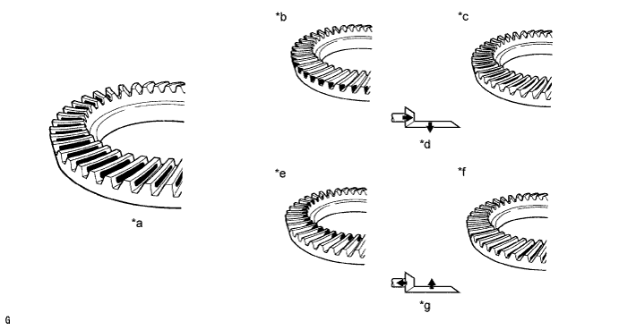
| *a | Proper Contact | *b | Heel Contact |
| *c | Face Contact | *d | Select an adjusting washer that brings the drive pinion closer to the ring gear |
| *e | Toe Contact | *f | Flank Contact |
| *g | Select an adjusting washer that shifts the drive pinion away from the ring gear | - | - |
| 8. INSPECT DIFFERENTIAL SIDE GEAR BACKLASH |
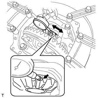 |
Place a dial indicator on the tip of a side gear tooth at a right angle. Hold the pinion gear in the rear differential case sub-assembly and check that the backlash.
| 9. INSPECT RUNOUT OF REAR DRIVE PINION COMPANION FLANGE SUB-ASSEMBLY |
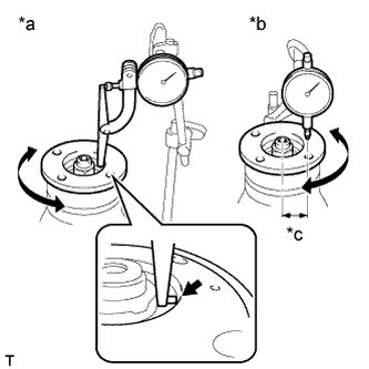 |
Using a dial indicator, measure the vertical and lateral runout of the rear drive pinion companion flange sub-assembly.
| *a | Vertical Runout |
| *b | Lateral Runout |
| *c | 30 mm (1.181 in.) |
| Item | Specified Condition |
| Vertical runout | 0.09 mm (0.00354 in.) |
| Lateral runout | 0.09 mm (0.00354 in.) |
| 10. INSPECT DIFFERENTIAL DRIVE PINION PRELOAD |
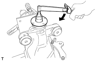 |
Using a torque wrench, measure the starting torque of the differential drive pinion.
| 11. INSPECT TOTAL PRELOAD |
|
Using a torque wrench, measure the preload with the teeth of the differential drive pinion and differential ring gear in contact.
| 12. REMOVE REAR DIFFERENTIAL SIDE GEAR SHAFT OIL SEAL |
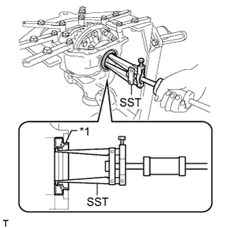 |
Using SST, remove the 2 rear differential side gear shaft oil seals.
| *1 | Rear Differential Side Gear Shaft Oil Seal |
| 13. REMOVE REAR DRIVE PINION NUT |
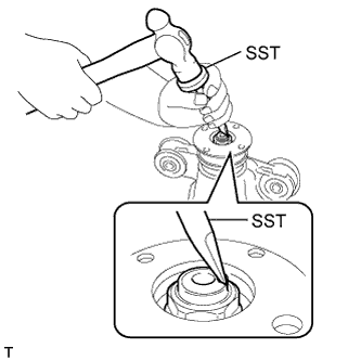 |
Using SST and a hammer, unstake the staked part of the rear drive pinion nut.
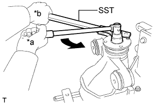 |
Using SST to hold the rear drive pinion companion flange, remove the rear drive pinion nut.
| *a | Turn |
| *b | Hold |
| 14. REMOVE REAR DRIVE PINION COMPANION FLANGE SUB-ASSEMBLY |
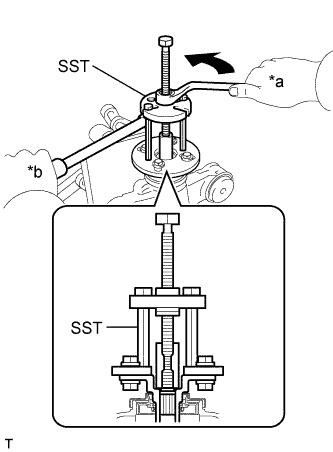 |
Using SST, remove the rear drive pinion companion flange sub-assembly.
| *a | Turn |
| *b | Hold |
| 15. REMOVE REAR DIFFERENTIAL DUST DEFLECTOR |
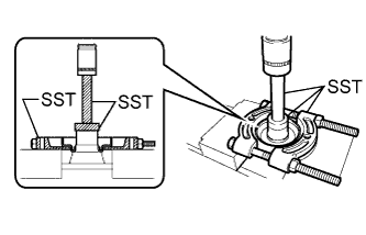 |
Using SST and a press, remove the rear differential dust deflector.
| 16. REMOVE REAR DIFFERENTIAL CARRIER OIL SEAL |
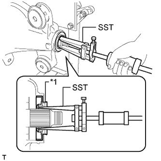 |
Using SST, remove the rear differential carrier oil seal from the rear differential carrier.
| *1 | Rear Differential Carrier Oil Seal |
| 17. REMOVE REAR DIFFERENTIAL DRIVE PINION OIL SLINGER |
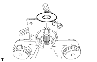 |
Remove the rear differential drive pinion oil slinger.
| 18. REMOVE REAR DRIVE PINION FRONT TAPERED ROLLER BEARING |
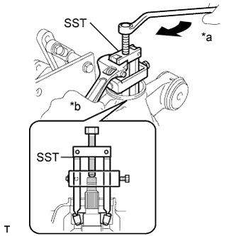 |
Using SST, remove the rear drive pinion front tapered roller bearing (inner race) from the differential drive pinion.
| *a | Turn |
| *b | Hold |
| 19. REMOVE REAR DIFFERENTIAL DRIVE PINION BEARING SPACER |
 |
Remove the rear differential drive pinion bearing spacer.
| 20. REMOVE REAR DIFFERENTIAL CASE SUB-ASSEMBLY |
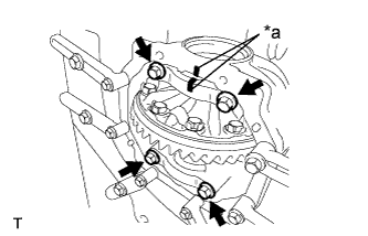 |
Put matchmarks on either the bearing cap and the rear differential carrier sub-assembly.
| *a | Matchmark |
Remove the 4 bolts and 2 bearing caps from the rear differential carrier sub-assembly.
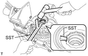 |
Using SST and a hammer, remove the 2 rear differential side gear shaft plate washers.
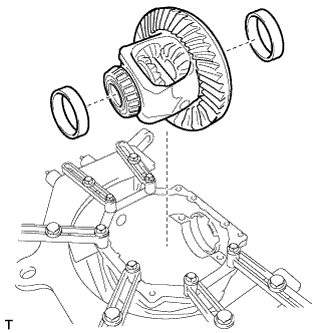 |
Remove the rear differential case sub-assembly and the rear differential case bearing outer races differential ring gear back side and differential ring gear teeth side from the rear differential carrier.
| 21. REMOVE REAR DRIVE PINION REAR TAPERED ROLLER BEARING |
Remove the differential drive pinion from the rear differential carrier sub-assembly.
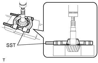 |
Using SST and a press, remove the rear drive pinion rear tapered roller bearing (inner race) from the differential drive pinion.
Remove the rear differential drive pinion plate washer from the differential drive pinion.
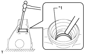 |
Using a brass bar and a hammer, remove the rear drive pinion rear tapered roller bearing (outer race) from the rear differential carrier sub-assembly.
| *1 | Outer Race |
| 22. REMOVE REAR DRIVE PINION FRONT TAPERED ROLLER BEARING |
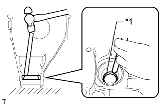 |
Using a brass bar and a hammer, remove the rear drive pinion front tapered roller bearing (outer race) from the rear differential carrier sub-assembly.
| *1 | Outer Race |
| 23. REMOVE DIFFERENTIAL RING GEAR |
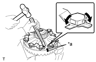 |
Hold the rear differential case sub-assembly in a vise between aluminum plates.
| *a | Matchmark |
Put matchmarks on the differential ring gear and the rear differential case sub-assembly.
Using a chisel and hammer, unstake the 5 rear differential ring gear set bolt lock plates.
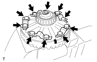 |
Remove the 10 rear differential ring gear set bolts and the 5 rear differential ring gear set bolt lock plates.
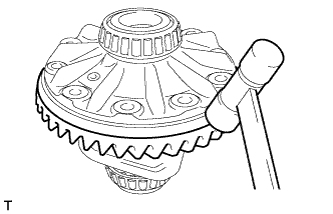 |
Using a plastic-faced hammer, tap on the differential ring gear to separate it from the rear differential case sub-assembly.
| 24. INSPECT RUNOUT OF REAR DIFFERENTIAL CASE SUB-ASSEMBLY |
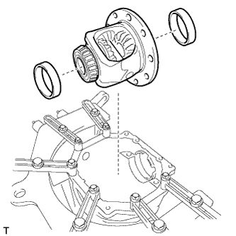 |
Install the rear differential case bearing outer races differential ring gear back side and differential ring gear teeth side to the rear differential case bearing inner races LH and RH respectively.
Install the rear differential case sub-assembly to the rear differential carrier sub-assembly.
Install the differential ring gear back side and differential ring gear teeth side rear differential side gear shaft plate washers so that there is no looseness in the rear differential case bearings.
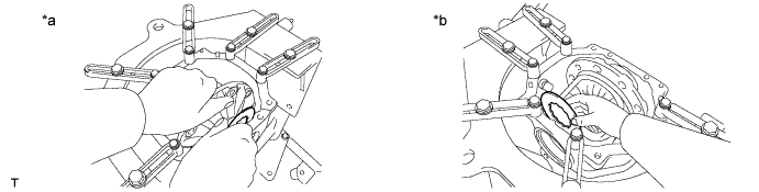
| *a | Differential Ring Gear Back Side | *b | Differential Ring Gear Teeth Side |
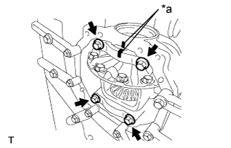 |
Align the matchmarks on the bearing cap and the rear differential carrier sub-assembly and install the 2 bearing caps.
| *a | Matchmark |
Tighten both bearing caps with the 4 bolts.
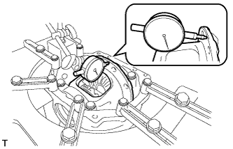 |
Using a dial indicator, measure the rear differential case sub-assembly runout.
Remove the 4 bolts and 2 bearing caps.
Remove the rear differential case sub-assembly and the rear differential case bearing outer races differential ring gear back side and differential ring gear teeth side from the rear differential carrier sub-assembly.
| 25. REMOVE REAR DIFFERENTIAL CASE BEARING |
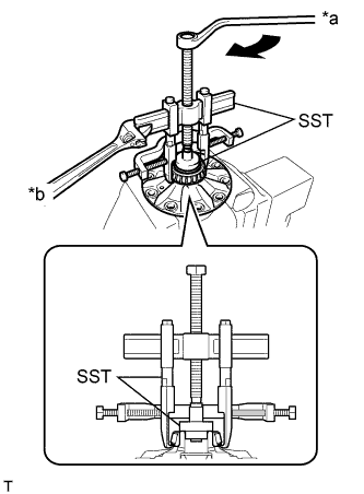 |
Hold the rear differential case sub-assembly in a vise between aluminum plates.
| *a | Turn |
| *b | Hold |
Using SST, remove the rear differential case bearing inner races LH and RH from the rear differential case sub-assembly.
| 26. INSPECT DIFFERENTIAL SIDE GEAR BACKLASH |
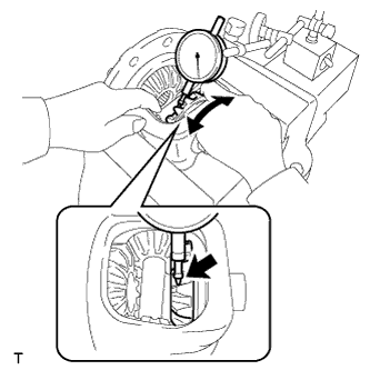 |
Secure the rear differential case sub-assembly in a vise between aluminum plates.
Place a dial indicator on the tip of a side gear tooth at a right angle. Hold the pinion gear in the rear differential case sub-assembly and check that the backlash.