 |
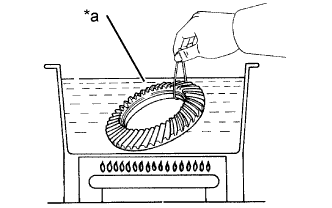
Heat the differential ring gear to approximately 100°C (212°F) in boiling water.
| *a | Boiling Water |
REAR DIFFERENTIAL CARRIER ASSEMBLY > REASSEMBLY |
| 1. INSTALL DIFFERENTIAL RING GEAR |
Clean the contact surfaces of the rear differential case sub-assembly and differential ring gear.
Clean the rear differential ring gear set bolt hole.
|
Heat the differential ring gear to approximately 100°C (212°F) in boiling water.
| *a | Boiling Water |
Carefully take the differential ring gear out of the boiling water.
Secure the rear differential case sub-assembly between aluminum plates in a vise.
After the moisture on the differential ring gear has completely evaporated, quickly install the differential ring gear to the rear differential case sub-assembly.
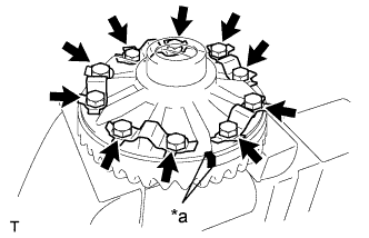 |
Align the matchmarks on the differential ring gear and rear differential case sub-assembly.
| *a | Matchmark |
Temporarily install 5 new rear differential ring gear set bolt lock plates with the 10 rear differential ring gear set bolts.
After the differential ring gear cools down, tighten the 10 ring gear set bolts uniformly.
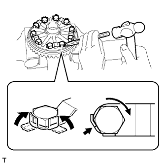 |
Using a chisel and hammer, stake the 5 rear differential ring gear set bolt lock plates.
Stake one claw so that it is flush against the flat surface of the bolt.
Stake the other claw against the surface of the bolt head to act as a stopper if the bolt starts to loosen.
| 2. INSTALL REAR DIFFERENTIAL CASE BEARING |
Using SST and a press, install the rear differential case bearing inner races LH and RH to the rear differential case sub-assembly.
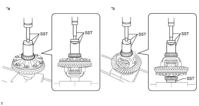
| *a | LH Side | *b | RH Side |
| 3. INSPECT RUNOUT OF DIFFERENTIAL RING GEAR |
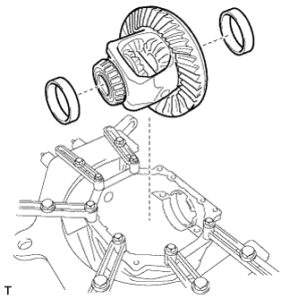 |
Install the rear differential case bearing outer races differential ring gear back side and differential ring gear teeth side to the rear differential case bearing inner races LH and RH respectively.
Install the rear differential case sub-assembly to the rear differential carrier.
Install the differential ring gear back side and differential ring gear teeth side rear differential side gear shaft plate washers so that there is no looseness in the rear differential case bearings.
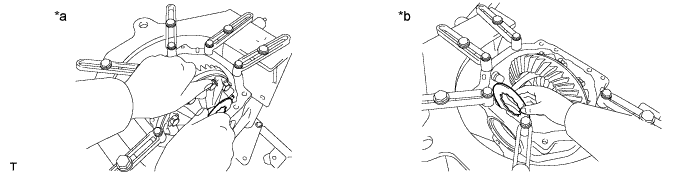
| *a | Differential Ring Gear Back Side | *b | Differential Ring Gear Teeth Side |
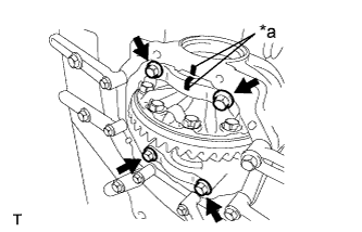 |
Align the matchmarks on the bearing cap and the rear differential carrier and install the 2 bearing caps.
| *a | Matchmark |
Tighten both bearing caps with the 4 bolts.
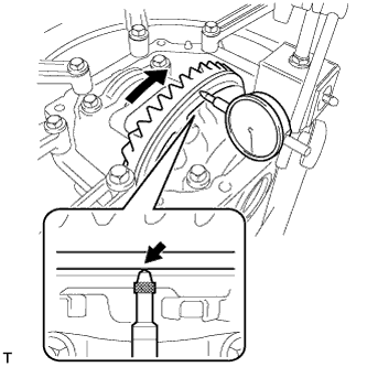 |
Using a dial indicator, measure the runout of the differential ring gear.
|
Remove the 4 bolts and 2 bearing caps.
| *a | Matchmark |
Remove the 2 rear differential side gear shaft plate washers.
|
Remove the rear differential case sub-assembly and the rear differential case bearing outer races differential ring gear back side and differential ring gear teeth side from the rear differential carrier.
| 4. INSTALL REAR DRIVE PINION REAR TAPERED ROLLER BEARING |
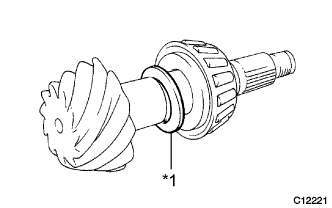 |
Install the rear differential drive pinion plate washer to the differential drive pinion.
| *1 | Rear Differential Drive Pinion Plate Washer |
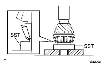 |
Using SST and a press, install the rear drive pinion rear tapered roller bearing (inner race) to the differential drive pinion.
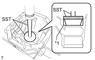 |
Using SST and a press, install the rear drive pinion rear tapered roller bearing (outer race) to the differential carrier assembly rear.
| *1 | Rear Drive Pinion Rear Tapered Roller Bearing (Outer Race) |
| 5. INSTALL REAR DRIVE PINION FRONT TAPERED ROLLER BEARING |
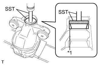 |
Using SST and a press, install the rear drive pinion front tapered roller bearing (outer race) to the differential carrier assembly rear.
| *1 | Rear Drive Pinion Front Tapered Roller Bearing (Outer Race) |
| 6. INSTALL REAR DIFFERENTIAL DUST DEFLECTOR |
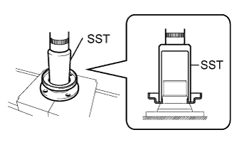 |
Using SST and a press, install a new rear differential dust deflector to the rear drive pinion companion flange.
| 7. ADJUST DIFFERENTIAL DRIVE PINION PRELOAD |
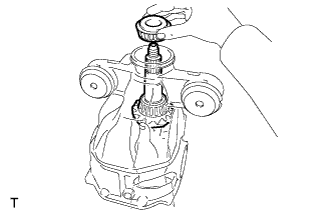 |
Install the differential drive pinion and the rear drive pinion front tapered roller bearing (inner race) to the differential carrier assembly rear.
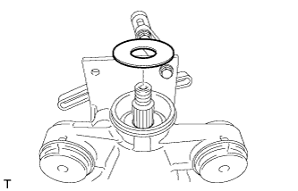 |
Install the rear differential drive pinion oil slinger to the differential carrier assembly rear.
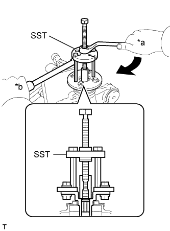 |
Using SST, install the rear drive pinion companion flange to the differential carrier assembly rear.
| *a | Turn |
| *b | Hold |
Coat the threads of a new rear drive pinion nut with hypoid gear oil LSD.
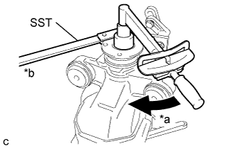 |
Using SST and a torque wrench, hold the rear drive pinion companion flange and tighten the rear drive pinion nut.
| *a | Turn |
| *b | Hold |
Turn the bearing clockwise and counterclockwise several times to stabilize it.
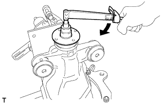 |
Using a torque wrench, measure the starting torque of the differential drive pinion.
| Item | Specified Condition |
| New rear drive pinion tapered roller bearing | 1.77 to 2.14 N*m (18.05 to 21.82 kgf*cm, 15.66 to 18.94 in.*lbf) |
| Reused rear drive pinion tapered roller bearing | 1.77 to 2.07 N*m (18.05 to 21.11 kgf*cm, 15.66 to 18.32 in.*lbf) |
| 8. INSTALL REAR DIFFERENTIAL CASE SUB-ASSEMBLY |
|
Install the rear differential case bearing outer races differential ring gear back side and differential ring gear teeth side to the rear differential case bearing inner races LH and RH respectively.
Install the rear differential case sub-assembly to the differential carrier assembly rear.
Install the differential ring gear back side and differential ring gear teeth side rear differential side gear shaft plate washers so that the rear differential case bearing is not loose.
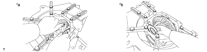
| *a | Differential Ring Gear Back Side | *b | Differential Ring Gear Teeth Side |
| 9. INSPECT AND ADJUST DIFFERENTIAL RING GEAR BACKLASH |
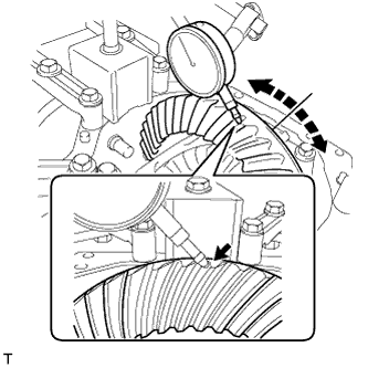 |
While holding the rear drive pinion companion flange, rotate the differential ring gear and measure the backlash.
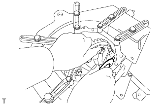 |
Select a new rear differential side gear shaft plate washer so that the differential ring gear backlash will be within the specified range, and install it to the differential ring gear back side.
| Part No. | Mark | Thickness | Part No. | Mark | Thickness |
| 90201-52001 | 01 | 2.58 mm (0.1016 in.) | 90564-46029 | 47 | 3.04 mm (0.1200 in.) |
| 90564-46014 | 32 | 2.60 mm (0.1024 in.) | 90201-52017 | 17 | 3.06 mm (0.1205 in.) |
| 90564-46015 | 33 | 2.62 mm (0.1031 in.) | 90564-46030 | 48 | 3.08 mm (0.1213 in.) |
| 90201-52003 | 03 | 2.64 mm (0.1039 in.) | 90564-46031 | 49 | 3.10 mm (0.1221 in.) |
| 90564-46016 | 34 | 2.66 mm (0.1047 in.) | 90201-52019 | 19 | 3.12 mm (0.1228 in.) |
| 90564-46017 | 35 | 2.68 mm (0.1055 in.) | 90564-46032 | 50 | 3.14 mm (0.1236 in.) |
| 90201-52005 | 05 | 2.70 mm (0.1063 in.) | 90564-46033 | 51 | 3.16 mm (0.1244 in.) |
| 90564-46018 | 36 | 2.72 mm (0.1070 in.) | 90201-52021 | 21 | 3.18 mm (0.1252 in.) |
| 90564-46019 | 37 | 2.74 mm (0.1078 in.) | 90564-46034 | 52 | 3.20 mm (0.1260 in.) |
| 90201-52007 | 07 | 2.76 mm (0.1087 in.) | 90564-46035 | 53 | 3.22 mm (0.1268 in.) |
| 90564-46020 | 38 | 2.78 mm (0.1094 in.) | 90201-52023 | 23 | 3.24 mm (0.1276 in.) |
| 90564-46021 | 39 | 2.80 mm (0.1102 in.) | 90564-46036 | 54 | 3.26 mm (0.1283 in.) |
| 90201-52009 | 09 | 2.82 mm (0.1110 in.) | 90564-46037 | 55 | 3.28 mm (0.1291 in.) |
| 90564-46022 | 40 | 2.84 mm (0.1118 in.) | 90201-52025 | 25 | 3.30 mm (0.1299 in.) |
| 90564-46023 | 41 | 2.86 mm (0.1126 in.) | 90564-46038 | 56 | 3.32 mm (0.1307 in.) |
| 90201-52011 | 11 | 2.88 mm (0.1134 in.) | 90564-46039 | 57 | 3.34 mm (0.1315 in.) |
| 90564-46024 | 42 | 2.90 mm (0.1142 in.) | 90201-52027 | 27 | 3.36 mm (0.1323 in.) |
| 90564-46025 | 43 | 2.92 mm (0.1150 in.) | 90564-46040 | 58 | 3.38 mm (0.1331 in.) |
| 90201-52013 | 13 | 2.94 mm (0.1157 in.) | 90564-46041 | 59 | 3.40 mm (0.1339 in.) |
| 90564-46026 | 44 | 2.96 mm (0.1165 in.) | 90201-52029 | 29 | 3.42 mm (0.1346 in.) |
| 90564-46027 | 45 | 2.98 mm (0.1173 in.) | 90564-46042 | 60 | 3.44 mm (0.1354 in.) |
| 90201-52015 | 15 | 3.00 mm (0.1181 in.) | 90564-46043 | 61 | 3.46 mm (0.1362 in.) |
| 90564-46028 | 46 | 3.02 mm (0.1189 in.) | 90201-52031 | 31 | 3.48 mm (0.1370 in.) |
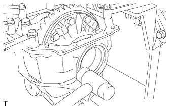 |
Make the rear differential case bearing and the rear differential side gear shaft plate washer snug by tapping on the rear differential carrier with a plastic-faced hammer.
|
Set a dial indicator perpendicular to the end of the differential ring gear face.
While holding the rear drive pinion companion flange, rotate the differential ring gear and measure the backlash.
|
If the backlash is not within the specified range, select a new rear differential side gear shaft plate washer so that the differential ring gear backlash will be within the specified range, and install it to the differential ring gear back side.
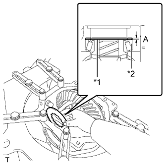 |
Select a thicker rear differential side gear shaft plate washer so that the clearance (A) becomes zero or close to zero.
| *1 | Rear Differential Side Gear Shaft Plate Washer |
| *2 | Rear Differential Case Bearing LH |
|
Make the rear differential case bearing and the rear differential side gear shaft plate washer snug by tapping on the rear differential carrier with a plastic-faced hammer.
|
Set a dial indicator perpendicular to the end of the differential ring gear face.
While holding the rear drive pinion companion flange, rotate the differential ring gear and measure the backlash.
| 10. ADJUST REAR DIFFERENTIAL CASE BEARING PRELOAD |
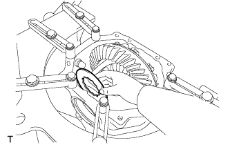 |
After adjusting the backlash of the differential ring gear, remove the differential ring gear teeth side rear differential side gear shaft plate washer.
Using a micrometer, measure the thickness of the removed rear differential side gear shaft plate washer.
Select a new rear differential side gear shaft plate washer which is 0.06 to 0.09 mm (0.00236 to 0.00354 in.) thicker than the removed one.
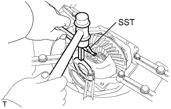 |
Using SST and a plastic-faced hammer, drive in the rear differential side gear shaft plate washer.
|
Align the matchmarks on the bearing cap and rear differential carrier and install the 2 bearing caps.
| *a | Matchmark |
Tighten both bearing caps with the 4 bolts.
|
Set a dial indicator perpendicular to the end of the differential ring gear face.
While holding the rear drive pinion companion flange, rotate the differential ring gear and measure the backlash.
| 11. INSPECT TOTAL PRELOAD |
|
Using a torque wrench, measure the preload with the teeth of the differential drive pinion and the differential ring gear in contact.
| Item | Specified Condition | |
| New rear drive pinion tapered roller bearing | New differential case bearing | 2.17 to 2.77 N*m (22.13 to 28.25 kgf*cm, 19.21 to 24.52 in.*lbf) |
| Reused differential case bearing | 2.09 to 2.67 N*m (21.31 to 27.23 kgf*cm, 18.50 to 23.63 in.*lbf) | |
| Reused rear drive pinion tapered roller bearing | New differential case bearing | 2.17 to 2.70 N*m (22.13 to 27.53 kgf*cm, 19.21 to 23.90 in.*lbf) |
| Reused differential case bearing | 2.09 to 2.60 N*m (21.31 to 26.51 kgf*cm, 18.50 to 23.01 in.*lbf) | |
|
Set a dial indicator to the end of the differential ring gear face.
While holding the rear drive pinion companion flange, rotate the differential ring gear and measure the backlash.
| 12. INSPECT TOOTH CONTACT BETWEEN RING GEAR AND DRIVE PINION |
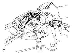 |
Coat 3 or 4 teeth at 3 different positions on the differential ring gear with Prussian blue.
Rotate the differential ring gear in both directions.
Inspect the tooth contact pattern.
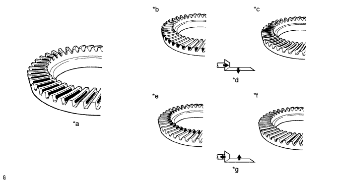
| *a | Proper Contact | *b | Heel Contact |
| *c | Face Contact | *d | Select an adjusting washer that brings the drive pinion closer to the ring gear |
| *e | Toe Contact | *f | Flank Contact |
| *g | Select an adjusting washer that shifts the drive pinion away from the ring gear | - | - |
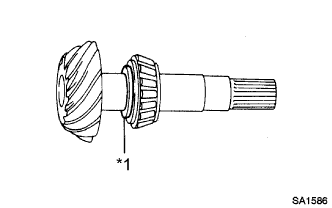 |
If the teeth are not contacting properly, use the following table to select a proper rear differential drive pinion plate washer for correction.
| *1 | Rear Differential Drive Pinion Plate Washer |
| Part No. | Mark | Thickness | Part No. | Mark | Thickness |
| 90201-35497 | - | 1.70 mm (0.0669 in.) | 90201-35508 | - | 2.03 mm (0.0799 in.) |
| 90201-35498 | - | 1.73 mm (0.0681 in.) | 90201-35509 | - | 2.06 mm (0.0811 in.) |
| 90201-35499 | - | 1.76 mm (0.0693 in.) | 90201-35510 | - | 2.09 mm (0.0823 in.) |
| 90201-35500 | - | 1.79 mm (0.0705 in.) | 90201-35511 | - | 2.12 mm (0.0795 in.) |
| 90201-35501 | - | 1.82 mm (0.0717 in.) | 90201-35512 | - | 2.15 mm (0.0846 in.) |
| 90201-35502 | - | 1.85 mm (0.0728 in.) | 90201-35513 | - | 2.18 mm (0.0858 in.) |
| 90201-35503 | - | 1.88 mm (0.0740 in.) | 90201-35514 | - | 2.21 mm (0.0870 in.) |
| 90201-35504 | - | 1.91 mm (0.0752 in.) | 90201-35515 | 01 | 2.24 mm (0.0882 in.) |
| 90201-35505 | - | 1.94 mm (0.0764 in.) | 90201-35516 | 02 | 2.27 mm (0.0894 in.) |
| 90201-35506 | - | 1.97 mm (0.0776 in.) | 90201-35517 | 03 | 2.30 mm (0.0906 in.) |
| 90201-35507 | - | 2.00 mm (0.0787 in.) | 90201-35518 | 04 | 2.33 mm (0.0917 in.) |
| 13. REMOVE REAR DRIVE PINION NUT |
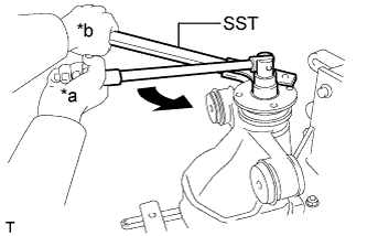 |
Using SST to hold the rear drive pinion companion flange, remove the differential carrier assembly rear.
| *a | Turn |
| *b | Hold |
| 14. REMOVE REAR DRIVE PINION COMPANION FLANGE SUB-ASSEMBLY |
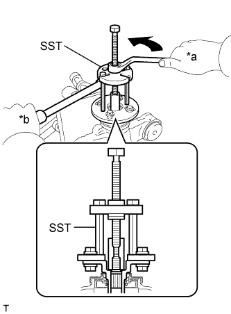 |
Using SST, remove the rear drive pinion companion flange sub-assembly.
| *a | Turn |
| *b | Hold |
| 15. REMOVE REAR DIFFERENTIAL DRIVE PINION OIL SLINGER |
|
Remove the rear differential drive pinion oil slinger.
| 16. REMOVE REAR DRIVE PINION FRONT TAPERED ROLLER BEARING |
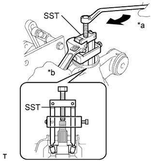 |
Using SST, remove the rear drive pinion front tapered roller bearing (inner race) from the differential drive pinion.
| *a | Turn |
| *b | Hold |
| 17. INSTALL REAR DIFFERENTIAL DRIVE PINION BEARING SPACER |
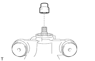 |
Install a new rear differential drive pinion bearing spacer to the differential drive pinion.
| 18. INSTALL REAR DRIVE PINION FRONT TAPERED ROLLER BEARING |
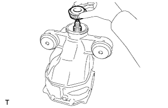 |
Install the rear drive pinion front tapered roller bearing (inner race) to the differential drive pinion.
| 19. INSTALL REAR DIFFERENTIAL DRIVE PINION OIL SLINGER |
|
Install the rear differential drive pinion oil slinger to the differential drive pinion.
| 20. INSTALL REAR DRIVE PINION COMPANION FLANGE SUB-ASSEMBLY |
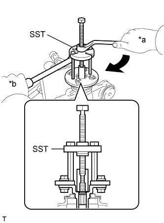 |
Using SST, install the rear drive pinion companion flange.
| *a | Turn |
| *b | Hold |
| 21. REMOVE REAR DRIVE PINION COMPANION FLANGE SUB-ASSEMBLY |
|
Using SST, remove the rear drive pinion companion flange sub-assembly.
| *a | Turn |
| *b | Hold |
| 22. INSTALL REAR DIFFERENTIAL CARRIER OIL SEAL |
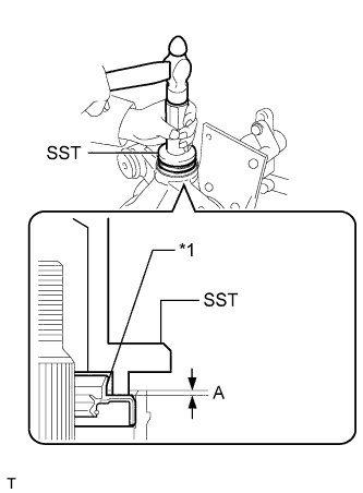 |
Using SST and a hammer, install the new rear differential carrier oil seal.
| *1 | Rear Differential Carrier Oil Seal |
Apply MP grease to the rear differential carrier oil seal lip.
| 23. INSTALL REAR DRIVE PINION COMPANION FLANGE SUB-ASSEMBLY |
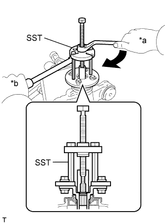 |
Using SST, install the rear drive pinion companion flange.
| *a | Turn |
| *b | Hold |
Coat the threads of the rear drive pinion nut with hypoid gear oil LSD.
|
Using SST and a torque wrench, hold the rear drive pinion companion flange and tighten the rear drive pinion nut.
| *a | Turn |
| *b | Hold |
| 24. ADJUST DIFFERENTIAL DRIVE PINION PRELOAD |
|
Using a torque wrench, measure the starting torque of the differential drive pinion.
| Item | Specified Condition |
| New rear drive pinion tapered roller bearing | 1.87 to 2.24 N*m (19.07 to 22.84 kgf*cm, 16.55 to 19.83 in.*lbf) |
| Reused rear drive pinion tapered roller bearing | 1.87 to 2.17 N*m (19.07 to 22.13 kgf*cm, 16.55 to 19.21 in.*lbf) |
| 25. INSPECT TOTAL PRELOAD |
|
Using a torque wrench, measure the preload with the teeth of the drive pinion and ring gear in contact.
| Item | Specified Condition | |
| New rear drive pinion tapered roller bearing | New differential case bearing | 2.27 to 2.87 N*m (23.15 to 29.27 kgf*cm, 20.09 to 25.40 in.*lbf) |
| Reused differential case bearing | 2.19 to 2.77 N*m (22.33 to 28.25 kgf*cm, 19.38 to 24.52 in.*lbf) | |
| Reused rear drive pinion tapered roller bearing | New differential case bearing | 2.27 to 2.80 N*m (23.15 to 28.55 kgf*cm, 20.09 to 24.78 in.*lbf) |
| Reused differential case bearing | 2.19 to 2.70 N*m (22.33 to 27.53 kgf*cm, 19.38 to 23.90 in.*lbf) | |
| 26. INSPECT DIFFERENTIAL RING GEAR BACKLASH |
Set a dial indicator perpendicular to the end of the differential ring gear face.
|
While holding the rear drive pinion companion flange, rotate the differential ring gear and measure the backlash.
| 27. INSPECT RUNOUT OF REAR DRIVE PINION COMPANION FLANGE SUB-ASSEMBLY |
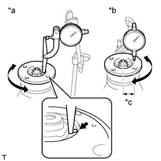 |
Using a dial indicator, measure the vertical and lateral runout of the rear drive pinion companion flange.
| *a | Vertical Runout |
| *b | Lateral Runout |
| *c | 30 mm (1.181 in.) |
| Item | Specified Condition |
| Vertical runout | 0.09 mm (0.00354 in.) |
| Lateral runout | 0.09 mm (0.00354 in.) |
| 28. STAKE REAR DRIVE PINION NUT |
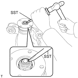 |
Using SST and a hammer, stake the rear drive pinion nut.
| 29. INSTALL REAR DIFFERENTIAL SIDE GEAR SHAFT OIL SEAL |
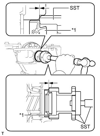 |
Using SST and a hammer, install a new 2 rear differential side gear shaft oil seals.
| *1 | Rear Differential Side Gear Shaft Oil Seal |
| 30. INSTALL REAR DIFFERENTIAL DRAIN PLUG |
Using a hexagon wrench 10 mm, install the rear differential drain plug and a new gasket.
| 31. REMOVE REAR DIFFERENTIAL CARRIER SUB-ASSEMBLY |
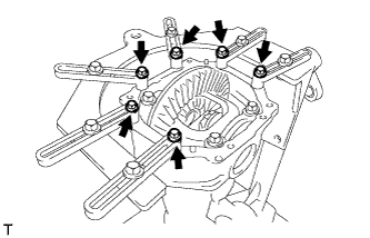 |
Remove the rear differential carrier sub-assembly from the overhaul stand.
| 32. INSTALL REAR DIFFERENTIAL BREATHER PLUG OIL DEFLECTOR |
Clean the seal packing attached to the rear differential carrier and the rear differential carrier cover using a scraper and wire brush. Then, remove the oil with a non-residue solvent or equivalent.
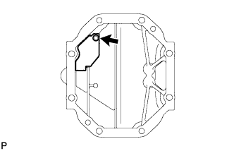 |
Install the rear differential breather plug oil deflector to the rear differential carrier cover with the bolt.
| 33. INSTALL REAR DIFFERENTIAL CARRIER COVER |
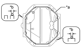 |
Apply seal packing to the rear differential carrier cover as shown in the illustration.
| *a | Seal packing |
| *b | 2 to 3 mm (0.0787 to 0.118 in.) |
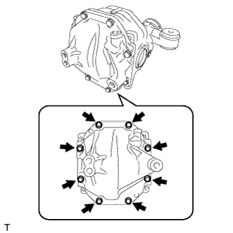 |
Install the rear differential carrier cover with the 8 bolts.
| 34. INSTALL REAR DIFFERENTIAL BREATHER PLUG |
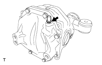 |
Install the rear differential breather plug to the rear differential carrier cover.