 |
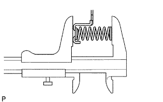
Using a vernier caliper, measure the free length of the spring together with the spring seat.
- Standard free length:
- 23.74 mm (0.935 in.)
AUTOMATIC TRANSMISSION UNIT > INSPECTION |
| 1. INSPECT 1ST AND REVERSE BRAKE RETURN SPRING SUB-ASSEMBLY |
|
Using a vernier caliper, measure the free length of the spring together with the spring seat.
| 2. INSPECT REAR PLANETARY GEAR ASSEMBLY |
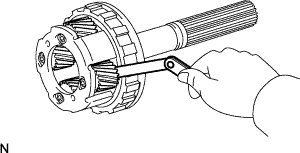 |
Using a feeler gauge, measure the rear planetary gear pinion thrust clearance.
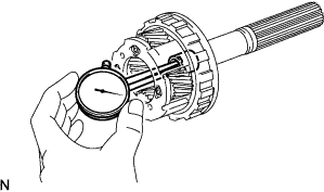 |
Using a caliper gauge, measure the inside diameter of the rear planetary gear bushing.
| 3. INSPECT PACK CLEARANCE OF NO. 4 BRAKE |
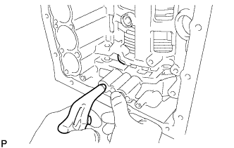 |
Make sure that the 1st and reverse brake piston moves smoothly when applying and releasing compressed air (392 kPa, 4.0 kgf/cm2, 57 psi).
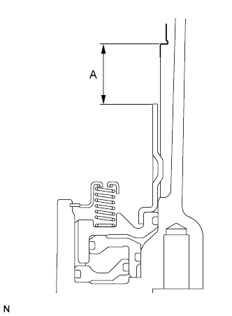 |
Using a vernier caliper, measure the level difference (dimension A) between the upper surface of the brake apply tube and the contact surface of the No. 4 brake flange at both ends across the 1st and reverse brake piston diameter, and calculate the average.
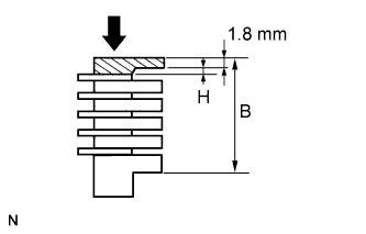 |
Using a vernier caliper, and while applying compression of 4.9 N (0.5 kgf, 1.1 lbf) or less, measure the thickness (dimension B) of the 2 No. 4 brake flanges, 4 No. 4 brake plates and the 5 No. 4 brake discs altogether at both ends across a diameter, and calculate the average.
If the pack clearance is outside the standard range, select and install a No. 4 brake flange that brings the pack clearance to be within the standard range.
| Part No. | Mark | Thickness H |
| SU003-05642 | 0 | 0 mm (0 in.) |
| SU003-05643 | 1 | 0.17 mm (0.00669 in.) |
| SU003-05644 | 3 | 0.31 mm (0.0122 in.) |
| SU003-05645 | 4 | 0.45 mm (0.0177 in.) |
| SU003-05646 | 5 | 0.59 mm (0.0232 in.) |
| SU003-05647 | 7 | 0.73 mm (0.0287 in.) |
| SU003-05648 | 8 | 0.87 mm (0.0343 in.) |
| SU003-05649 | 10 | 1.01 mm (0.0398 in.) |
| SU003-05650 | 11 | 1.15 mm (0.0453 in.) |
| SU003-05651 | 12 | 1.29 mm (0.0508 in.) |
| 4. INSPECT NO. 4 BRAKE DISC |
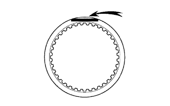 |
Check whether the sliding surfaces of the discs, plates and the flanges are worn or burnt.
If necessary, replace them.
| 5. INSPECT INTERMEDIATE SHAFT |
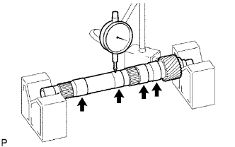 |
Using a dial indicator, check the intermediate shaft runout.
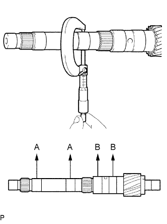 |
Using a micrometer, check the outer diameter of the intermediate shaft at each point shown in the illustration.
| 6. INSPECT NO. 3 ONE-WAY CLUTCH ASSEMBLY |
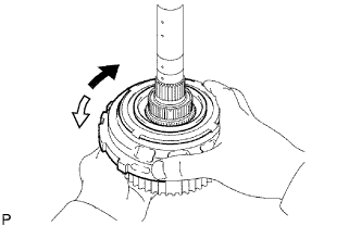 |
Hold the rear planetary ring gear flange sub-assembly and turn the No. 3 one-way clutch assembly.
 | Lock |
 | Free |
Check that the No. 3 one-way clutch assembly turns freely when turned counterclockwise and locks when turned clockwise.
If there is a problem with the No. 3 one-way clutch assembly, replace it.
| 7. INSPECT CENTER PLANETARY GEAR ASSEMBLY |
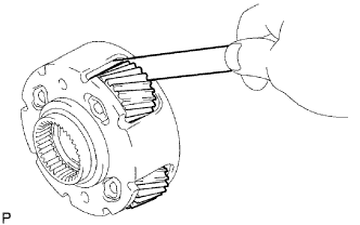 |
Using a feeler gauge, measure the center planetary gear pinion thrust clearance.
| 8. INSPECT NO. 2 BRAKE DISC |
|
Check whether the sliding surfaces of the discs, plates and the flanges are worn or burnt.
If necessary, replace them.
| 9. INSPECT NO. 2 BRAKE PISTON RETURN SPRING SUB-ASSEMBLY |
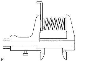 |
Using a vernier caliper, measure the free length of the spring together with the spring seat.
| 10. INSPECT PISTON STROKE OF NO. 2 BRAKE PISTON |
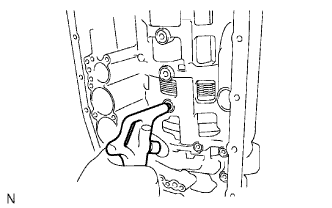 |
Make sure that the No. 2 brake piston moves smoothly when applying and releasing compressed air (392 kPa, 4.0 kgf/cm2, 57 psi).
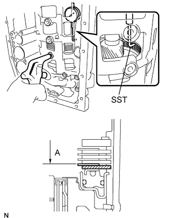 |
Using SST and a dial indicator, measure the moving distance (distance A) of the No. 2 brake disc at both ends across a diameter while blowing air (392 kPa, 4.0 kgf/cm2, 57 psi) into the oil hole as shown in the illustration, and calculate the average.
If the piston stroke is outside the standard range, select and install a No. 2 brake flange that brings the piston stroke within the standard range.
| Part No. | Mark | Thickness |
| SU003-03771 | 0 | 2.0 mm (0.0787 in.) |
| SU003-03772 | 1 | 2.1 mm (0.0827 in.) |
| SU003-03773 | 2 | 2.2 mm (0.0866 in.) |
| SU003-03774 | 3 | 2.3 mm (0.0906 in.) |
| SU003-03775 | 4 | 2.4 mm (0.0945 in.) |
| SU003-03776 | 5 | 2.5 mm (0.0984 in.) |
| SU003-03777 | 6 | 2.6 mm (0.102 in.) |
| SU003-03778 | 7 | 2.7 mm (0.106 in.) |
| 11. INSPECT BRAKE PISTON RETURN SPRING SUB-ASSEMBLY |
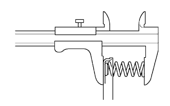 |
Using a vernier caliper, measure the free length of the spring together with the spring seat.
| 12. INSPECT FRONT PLANETARY GEAR ASSEMBLY |
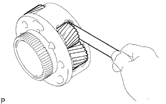 |
Using a feeler gauge, measure the front planetary gear pinion thrust clearance.
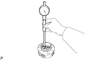 |
Using a cylinder gauge, measure the inside diameter of the front planetary gear bushing.
| 13. INSPECT ONE-WAY CLUTCH ASSEMBLY |
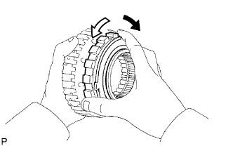 |
Install the one-way clutch assembly to the one-way clutch inner race sub-assembly.
| Lock |
| Free |
Hold the one-way clutch inner race sub-assembly and turn the one-way clutch assembly.
Check that the one-way clutch assembly turns freely when turned counterclockwise and locks when turned clockwise.
If there is a problem with the one-way clutch assembly, replace it.
Remove the one-way clutch assembly from the one-way clutch inner race sub-assembly.
| 14. INSPECT PISTON STROKE OF NO. 1 BRAKE PISTON |
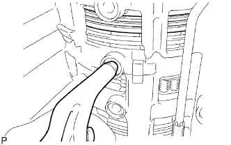 |
Make sure that the No. 1 brake piston moves smoothly when applying and releasing compressed air (392 kPa, 4.0 kgf/cm2, 57 psi).
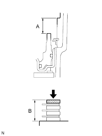 |
Using a vernier caliper, and while applying compression of 4.9 N (0.5 kgf, 1.1 lbf) or less, measure the level difference (dimension A) between the upper surface of the No. 1 brake piston and the contact surface of the No. 1 brake flange at both ends across the No. 1 brake piston diameter.
Using a vernier caliper, measure the thickness (dimension B) of the No. 1 brake flange, 3 No. 1 brake plates and the 3 No. 1 brake discs altogether at both ends across a diameter, and calculate the average.
If the piston stroke is outside the standard range, parts may have been assembled incorrectly, so check and reassemble them again.
If the piston stroke is still outside the standard range, select another No. 1 brake flange that brings the piston stroke within the standard range.
| Part No. | Mark | Thickness |
| SU003-03765 | 0 | 2.0 mm (0.0787 in.) |
| SU003-03766 | 1 | 2.2 mm (0.0866 in.) |
| SU003-03767 | 2 | 2.4 mm (0.0945 in.) |
| SU003-03768 | 3 | 2.6 mm (0.102 in.) |
| 15. INSPECT NO. 1 BRAKE DISC |
|
Check whether the sliding surfaces of the discs, plates and the flange are worn or burnt.
If necessary, replace them.
| 16. INSPECT NO. 3 BRAKE PISTON RETURN SPRING SUB-ASSEMBLY |
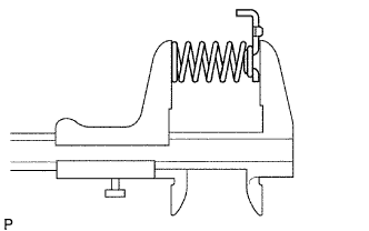 |
Using a vernier caliper, measure the free length of the spring together with the spring seat.
| 17. INSPECT NO. 3 BRAKE DISC (2ND BRAKE DISC SET) |
|
Check whether the sliding surfaces of the discs, plates and the flange are worn or burnt.
If necessary, replace them.
| 18. INSPECT NO. 2 ONE-WAY CLUTCH ASSEMBLY |
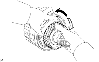 |
Hold the reverse clutch hub sub-assembly and turn the No. 2 one-way clutch assembly.
| Lock |
| Free |
Check that the No. 2 one-way clutch assembly turns freely when turned clockwise and locks when turned counterclockwise.
If there is a problem with the No. 2 one-way clutch assembly, replace it.
| 19. INSPECT INDIVIDUAL PISTON OPERATION |
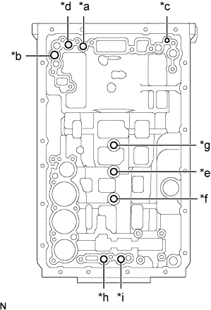 |
Check the operating sound while applying compressed air into the oil holes indicated in the illustration.
| *a | No. 1 Clutch |
| *b | No. 2 Clutch |
| *c | No. 3 Clutch |
| *d | No. 4 Clutch |
| *e | No. 1 Brake |
| *f | No. 2 Brake |
| *g | No. 3 Brake |
| *h | No. 4 Brake (In) |
| *i | No. 4 Brake (Out) |
| 20. INSPECT NO. 4 ONE-WAY CLUTCH ASSEMBLY |
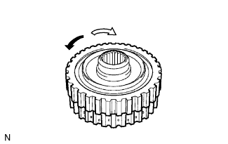 |
Hold the coast clutch hub sub-assembly and turn the No. 4 one-way clutch assembly.
| Lock |
| Free |
Check that the No. 4 one-way clutch assembly turns freely when turned clockwise and locks when turned counterclockwise.
If there is a problem with the No. 4 one-way clutch assembly, replace it.
| 21. INSPECT DIRECT CLUTCH RETURN SPRING SUB-ASSEMBLY |
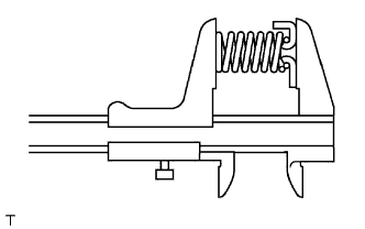 |
Using a vernier caliper, measure the free length of the spring together with the spring seat.
| 22. INSPECT REVERSE CLUTCH RETURN SPRING SUB-ASSEMBLY |
|
Using a vernier caliper, measure the free length of the spring together with the spring seat.
| 23. INSPECT NO. 2 CLUTCH DISC (DIRECT CLUTCH DISC) |
|
Check whether the sliding surfaces of the discs, plates and the flange are worn or burnt.
If necessary, replace them.
| 24. INSPECT PACK CLEARANCE OF NO. 2 CLUTCH |
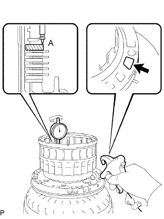 |
Using a dial indicator, measure the moving distance (distance A) of the direct clutch flange at both ends across a diameter while blowing air (392 kPa, 4.0 kgf/cm2, 57 psi) into the oil hole as shown in the illustration, and calculate the average.
If the pack clearance is outside the standard range, select and install a direct clutch flange that brings the pack clearance within the standard range.
| Part No. | Mark | Thickness |
| SU003-03756 | 0 | 3.0 mm (0.118 in.) |
| SU003-03757 | 1 | 3.1 mm (0.122 in.) |
| SU003-03758 | 2 | 3.2 mm (0.126 in.) |
| SU003-03759 | 3 | 3.3 mm (0.130 in.) |
| SU003-03760 | 4 | 3.4 mm (0.134 in.) |
| SU003-03761 | 5 | 3.5 mm (0.138 in.) |
| SU003-03762 | 6 | 3.6 mm (0.142 in.) |
| SU003-03763 | 7 | 3.7 mm (0.146 in.) |
| SU003-03764 | 8 | 3.8 mm (0.150 in.) |
| 25. INSPECT PACK CLEARANCE OF NO. 3 CLUTCH |
Using a dial indicator, measure the reverse clutch piston stroke (distance A) and the moving distance (distance B) of the reverse clutch flange at both ends across a diameter while blowing air (392 kPa, 4.0 kgf/cm2, 57 psi) into the oil hole as shown in the illustration, and calculate the average.
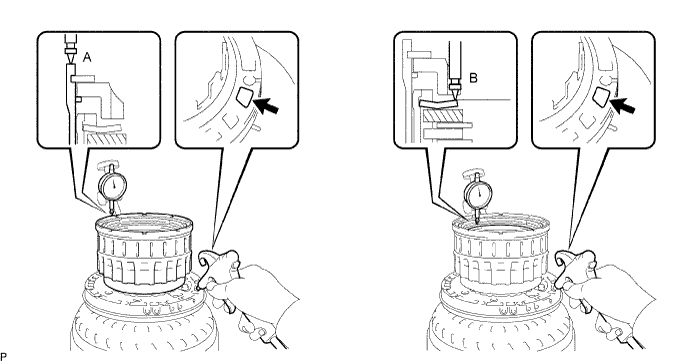
If the pack clearance is outside the standard range, select and install a reverse clutch flange that brings the pack clearance within the standard range.
| Part No. | Mark | Thickness |
| SU003-03725 | 0 | 2.4 mm (0.0945 in.) |
| SU003-03726 | 1 | 2.5 mm (0.0984 in.) |
| SU003-03727 | 2 | 2.6 mm (0.102 in.) |
| SU003-03728 | 3 | 2.7 mm (0.106 in.) |
| SU003-03729 | 4 | 2.8 mm (0.110 in.) |
| SU003-03730 | 5 | 2.9 mm (0.114 in.) |
| SU003-03731 | 6 | 3.0 mm (0.118 in.) |
| SU003-03732 | 7 | 3.1 mm (0.122 in.) |
| SU003-03733 | 8 | 3.2 mm (0.126 in.) |
| SU003-03734 | 9 | 3.3 mm (0.130 in.) |
| SU003-03735 | A | 3.4 mm (0.134 in.) |
| SU003-03736 | B | 3.5 mm (0.138 in.) |
| 26. INSPECT FORWARD CLUTCH RETURN SPRING SUB-ASSEMBLY |
|
Using a vernier caliper, measure the free length of the spring together with the spring seat.
| 27. INSPECT NO. 4 CLUTCH DISC (COAST CLUTCH DISC) |
|
Check whether the sliding surfaces of the discs, plates and the flange are worn or burnt.
If necessary, replace them.
| 28. INSPECT PACK CLEARANCE OF NO. 1 CLUTCH |
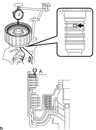 |
Using a dial indicator, measure the moving distance (distance A) of the forward clutch flange at both ends across a diameter while blowing air (196 kPa, 2.0 kgf/cm2, 28 psi) into the oil hole as shown in the illustration, and calculate the average.
If the pack clearance is outside the standard range, select and install a forward clutch flange that brings the pack clearance within the standard range.
| Part No. | Mark | Thickness |
| SU003-03712 | 0 | 3.0 mm (0.118 in.) |
| SU003-03713 | 1 | 3.1 mm (0.122 in.) |
| SU003-03714 | 2 | 3.2 mm (0.126 in.) |
| SU003-03715 | 3 | 3.3 mm (0.130 in.) |
| SU003-03716 | 4 | 3.4 mm (0.134 in.) |
| SU003-03717 | 5 | 3.5 mm (0.138 in.) |
| SU003-03718 | 6 | 3.6 mm (0.142 in.) |
| SU003-03719 | 7 | 3.7 mm (0.146 in.) |
| SU003-03720 | 8 | 3.8 mm (0.150 in.) |
| SU003-03721 | 9 | 3.9 mm (0.154 in.) |
| 29. INSPECT NO. 1 CLUTCH DISC (FORWARD CLUTCH DISC) |
|
Check whether the sliding surfaces of the discs, plates and the flange are worn or burnt.
If necessary, replace them.
| 30. INSPECT PACK CLEARANCE OF NO. 4 CLUTCH |
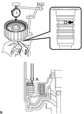 |
Using a dial indicator, measure the moving distance (distance A) of the coast clutch flange at both ends across a diameter while blowing air (196 kPa, 2.0 kgf/cm2, 28 psi) into the oil hole as shown in the illustration, and calculate the average.
If the pack clearance is outside the standard range, select and install a coast clutch flange that brings the pack clearance within the standard range.
| Part No. | Mark | Thickness |
| SU003-03746 | 0 | 3.0 mm (0.118 in.) |
| SU003-03747 | 1 | 3.1 mm (0.122 in.) |
| SU003-03748 | 2 | 3.2 mm (0.126 in.) |
| SU003-03749 | 3 | 3.3 mm (0.130 in.) |
| SU003-03750 | 4 | 3.4 mm (0.134 in.) |
| SU003-03751 | 5 | 3.5 mm (0.138 in.) |
| SU003-03752 | 6 | 3.6 mm (0.142 in.) |
| SU003-03753 | 7 | 3.7 mm (0.146 in.) |
| SU003-03754 | 8 | 3.8 mm (0.150 in.) |
| SU003-03755 | 9 | 3.9 mm (0.154 in.) |
| 31. INSPECT FORWARD CLUTCH HUB SUB-ASSEMBLY |
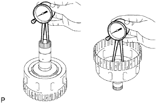 |
Using a caliper gauge, measure the inside diameter of the forward clutch hub bushing.
| 32. INSPECT NO. 3 CLUTCH DISC (REAR CLUTCH DISC) |
|
Check whether the sliding surfaces of the discs, plates and the flange are worn or burnt.
If necessary, replace them.
| 33. INSPECT REVERSE CLUTCH HUB SUB-ASSEMBLY |
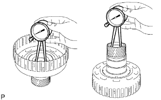 |
Using a caliper gauge, measure the inside diameter of the reverse clutch hub bushing.