Home › Engine / Hybrid System › FA20 INTAKE / EXHAUST › INTAKE MANIFOLD

INTAKE MANIFOLD > REMOVAL

for Preparation Click here


1. CHECK FUEL PUMP OPERATION AND INSPECT FOR FUEL LEAK
  1. Check fuel pressure.

    1. Connect the GTS to the DLC3.

    2. Start the engine.

    3. Turn the GTS on.

    4. Enter the following menus: Powertrain / Engine / Active Test / Control the Target Fuel Pressure.

    5. Check that the fuel pressure fluctuates when the target fuel pressure changes.

      HINT:
      The target fuel pressure operation lowers the target fuel pressure by -12.5% or increases the target fuel pressure by 24.8%.

      Standard:
      Fuel pressure fluctuates in accordance with the GTS operation.

      If the result is not as specified, replace the fuel pump or fuel pressure sensor.


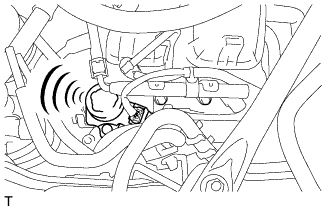
  1. Check operating sound.

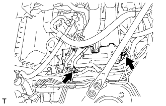
    1. Remove the injector cover (for bank 2).

    2. Start the engine.


    3. A281913
    4. Using a sound scope, check the operating sound of the pump.
      If no sound can be heard, check the fuel pump, wire harness and ECM.

    5. Stop the engine.

    6. Reinstall the injector cover (for bank 2).


2. DISCONNECT CABLE FROM NEGATIVE BATTERY TERMINAL


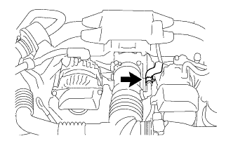
3. REMOVE AIR CLEANER CAP WITH AIR CLEANER HOSE


    A283417
  1. Loosen the hose clamp and disconnect the No. 2 ventilation hose.


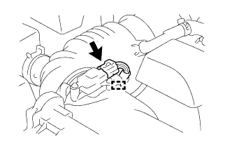
    A283418
  1. Disconnect the mass air flow meter connector.

  1. Disengage the clamp and separate the wire harness from the air cleaner cap.


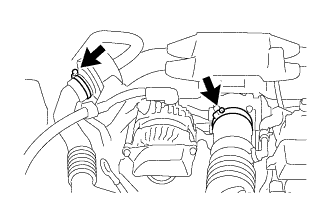
    A283419
  1. Loosen the 2 hose clamps.


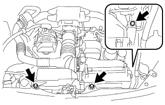
    A283420
  1. Remove the 3 bolts and the air cleaner cap with air cleaner hose.


4. REMOVE THROTTLE WITH MOTOR BODY ASSEMBLY


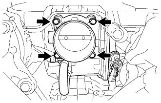
    A281135
  1. Remove the 4 bolts and and disconnect the throttle with motor body assembly.

  1. Remove the gasket.


5. REMOVE INJECTOR DRIVER


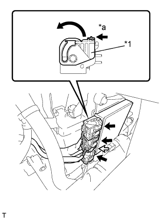
    A277974E02
  1. Move the lock levers in the direction indicated by the arrow to release the 3 connector locks. Disconnect the 4 connectors from the injector driver.
    Text in Illustration 
    *1
    Lock Lever
    *a
    Release
    V100135
    Lock with Connector
    V100136
    Normal Connector


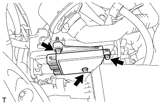
    A277975
  1. Remove the 3 bolts and injector driver.

    NOTICE:
    Be careful not to drop or strike the injector driver.


6. REMOVE INJECTOR COVER (for Bank 2)


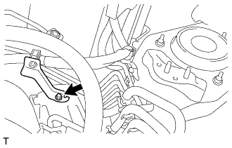
    A281164
  1. Remove the bolt and disconnect the wire harness clamp bracket from the injector cover (for bank 2).


    A277981
  1. Remove the 2 bolts and injector cover (for bank 2).


7. REMOVE INJECTOR COVER (for Bank 1)


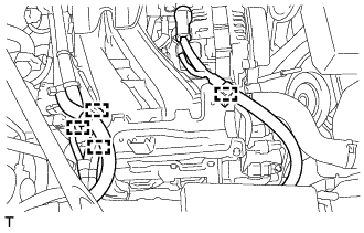
    A279751
  1. Disengage the 4 clamps and separate the wire harness from the injector cover (for bank 1).


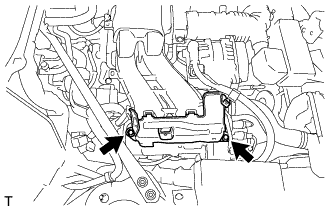
    A277976
  1. Remove the 2 bolts and injector cover (for bank 1).


8. DISCONNECT NO. 1 FUEL HOSE (for Clamp Type)


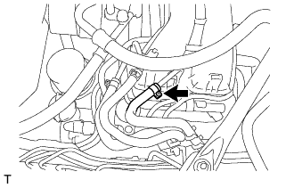
    A279753
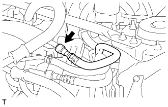
  1. Remove the clamp and disconnect the No. 1 fuel hose.

    NOTICE:
    1. Check for dirt or other foreign matter on the parts to be disconnected and clean them if necessary.
    2. Be careful not to splash the fuel.
    3. Receive the fuel remaining inside the fuel hose with a container.
    4. Check for dirt or other foreign matter on the parts to be disconnected and clean them if necessary.


9. DISCONNECT NO. 1 FUEL HOSE (for Metal Type)


    A281447
  1. Using SST, disconnect the No. 1 fuel hose from the fuel delivery pipe sub-assembly (Click here).

    SST
    SU003-03936  


10. DISCONNECT FUEL DELIVERY PIPE SUB-ASSEMBLY


A281446
  1. Remove the bolt and disconnect the fuel delivery pipe sub-assembly.

  1. Disconnect the No. 2 fuel vapor feed hose and move the fuel delivery pipe toward the front of the vehicle.


11. REMOVE NO. 1 ENGINE COVER SUB-ASSEMBLY (w/ Air Conditioning System)


    A276538E01
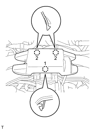
  1. Disengage the 3 craws and remove the No. 1 engine cover sub-assembly.

    HINT:
    Disengage the 3 craws in the order shown in the illustration.


12. DISCONNECT VACUUM TUBE CONNECTOR HOSE (for Manual Transmission)


    C264090E01
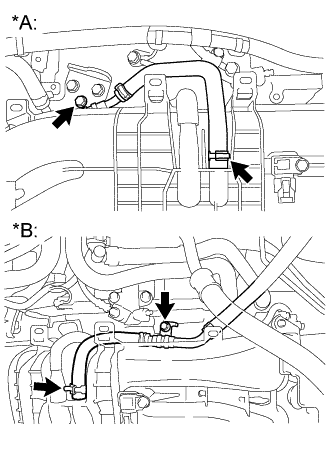
  1. Loosen the hose clamp and disconnect the union to check valve hose from the intake manifold.
    Text in Illustration 
    *A
    for LHD
    *B
    for RHD


13. DISCONNECT VENTILATION HOSE


    A280272
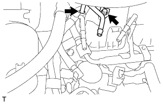
  1. Disconnect the ventilation hose.


14. REMOVE INTAKE MANIFOLD


    A276539
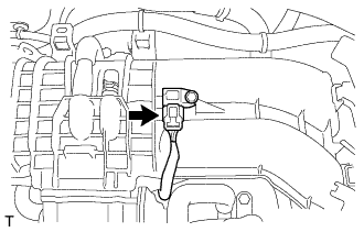
  1. Disconnect the manifold absolute pressure sensor connector.


    A281116
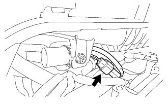
  1. Disconnect the purge valve connector.


    A280271
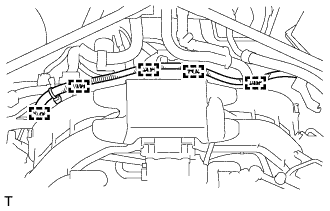
  1. Disengage the 5 clamps and disconnect the battery cable.


    A281444
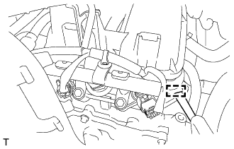
  1. Disengage the clamp and disconnect the engine wire harness.


    A281129E01
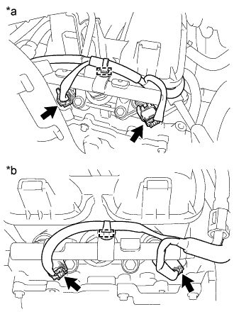
  1. Disengage the 2 clamps and disconnect the 4 connectors.
    Text in Illustration 
    *a
    for Bank 2
    *b
    for Bank 1


    A279755
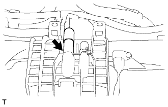
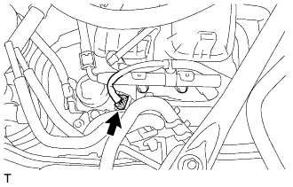
  1. Disconnect the fuel pump connector.


    A280273E01
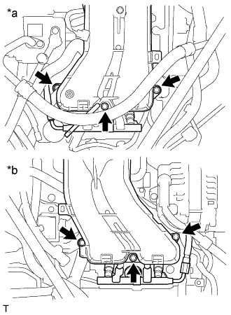
  1. Remove the 6 bolts, intake manifold and 2 gaskets.
    Text in Illustration 
    *a
    for Bank 2
    *b
    for Bank 1