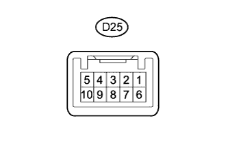
ENGINE IMMOBILISER SYSTEM (w/ Entry and Start System) > TERMINALS OF ECU |
| CHECK ENGINE SWITCH |
|
Measure the resistance and voltage according to the value(s) in the table below.
| Terminal No. (Symbol) | Input/Output | Wiring Color | Terminal Description | Condition | Specified Condition | Related Data List Item/DTC |
| D25-6 (AGND) - Body ground | - | B - Body ground | Transponder key amplifier ground | Always | Below 1 Ω | - |
| D25-7 (TXCT) - D25-6 (AGND) | Input | W - B | Clock signal | Engine switch off, brake pedal*1 or clutch pedal*2 not depressed, and 30 seconds or more after driver door opened and then closed | Below 1 V | - |
| D25-8 (CODE) - D25-6 (AGND) | Input/Output | R - B | Bidirectional data communication | Engine switch off, brake pedal*1 or clutch pedal*2 not depressed, and 30 seconds or more after driver door opened and then closed | Below 1 V | - |
| D25-10 (VC5) - D25-6 (AGND) | Input | G - B | Transponder key amplifier power supply | Engine switch off, brake pedal*1 or clutch pedal*2 not depressed, and 30 seconds or more after driver door opened and then closed | Below 1 V | - |
Check for pulses according to the value(s) in the table below.
| Terminal No. (Symbol) | Input/Output | Wiring Color | Terminal Description | Condition | Specified Condition | Related Data List Item/DTC |
| D25-7 (TXCT) - D25-6 (AGND) | Input | W - B | Clock signal | Engine switch off, key not inside vehicle, and within 30 seconds after engine switch pushed | Pulse generation (See waveform 1) |
|
| D25-8 (CODE) - D25-6 (AGND) | Output | R - B | Bidirectional data communication | Engine switch off, and engine switch pushed while key held against engine switch* | Pulse generation (See waveform 2) | |
| D25-10 (VC5) - D25-6 (AGND) | Input | G - B | Transponder key amplifier power supply | Engine switch off, key not inside vehicle, and within 30 seconds after engine switch pushed | Pulse generation (See waveform 3) |
Inspect using an oscilloscope.
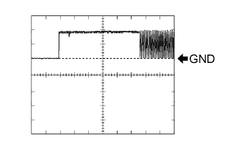 |
Waveform 1 (Reference)
| Item | Content |
| Tester Connection | D25-7 (TXCT) - D25-6 (AGND) |
| Tool Setting | 2 V/DIV., 20 ms./DIV. |
| Condition | Engine switch off, key not inside vehicle, and within 30 seconds after engine switch pushed |
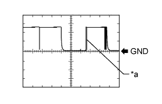 |
Waveform 2 (Reference)
| *a | Key held against engine switch |
| Item | Content |
| Tester Connection | D25-8 (CODE) - D25-6 (AGND) |
| Tool Setting | 2 V/DIV., 200 ms./DIV. |
| Condition | Engine switch off, and engine switch pushed while key held against engine switch* |
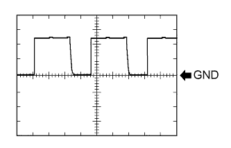 |
Waveform 3 (Reference)
| Item | Content |
| Tester Connection | D25-10 (VC5) - D25-6 (AGND) |
| Tool Setting | 2 V/DIV., 200 ms./DIV. |
| Condition | Engine switch off, key not inside vehicle, and within 30 seconds after engine switch pushed |
| CHECK CERTIFICATION ECU (SMART KEY ECU ASSEMBLY) |
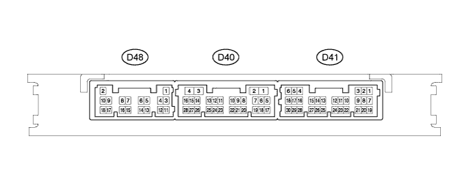
Disconnect the D48 certification ECU (smart key ECU assembly) connector.
Measure the resistance and voltage according to the value(s) in the table below.
| Terminal No. (Symbol) | Input/Output | Wiring Color | Terminal Description | Condition | Specified Condition | Related Data List Item/DTC |
| D48-2 (+B) - D48-11 (GND) | Input | W - BR | +B power supply | Always | 11 to 14 V | - |
| D48-11 (GND) - Body ground | - | BR - Body ground | Ground | Always | Below 1 Ω | - |
Reconnect the D48 certification ECU (smart key ECU assembly) connector.
Measure the resistance and voltage according to the value(s) in the table below.
| Terminal No. (Symbol) | Input/Output | Wiring Color | Terminal Description | Condition | Specified Condition | Related Data List Item/DTC |
| D41-5 (IG2) - D48-11 (GND) | Input | P - BR | Engine switch power supply | Engine switch off → on (IG) | Below 1 V → 11 to 14 V | Ignition Switch |
| D41-9 (TXCT) - D41-24 (AGND) | Output | BE - B | Clock signal | Engine switch off, brake pedal*1 or clutch pedal*2 not depressed, and 30 seconds or more after driver door opened and then closed | Below 1 V |
|
| D41-7 (CODE) - D41-24 (AGND) | Input | SB - B | Signal input from transponder key amplifier | Engine switch off, brake pedal*1 or clutch pedal*2 not depressed, and 30 seconds or more after driver door opened and then closed | Below 1 V | |
| D41-1 (VC5) - D41-24 (AGND) | Output | W - B | Transponder key amplifier power supply | Engine switch off, brake pedal*1 or clutch pedal*2 not depressed, and 30 seconds or more after driver door opened and then closed | Below 1 V | |
| D41-24 (AGND) - Body ground | - | B - Body ground | Transponder key amplifier ground | Always | Below 1 Ω | |
| D48-13 (EGIO) - D48-11 (GND)*3 | Input/Output | R - BR | EFI communication signal (certification ECU (smart key ECU assembly) to ECM) | Engine switch on (IG) | 11 to 14 V |
|
Check for pulses according to the value(s) in the table below.
| Terminal No. (Symbol) | Input/Output | Wiring Color | Terminal Description | Condition | Specified Condition | Related Data List Item/DTC |
| D41-9 (TXCT) - D41-24 (AGND) | Output | BE - B | Clock signal | Engine switch off, key not inside vehicle, and within 30 seconds after engine switch pushed | Pulse generation (See waveform 1) |
|
| D41-7 (CODE) - D41-24 (AGND) | Input | SB - B | Signal input from transponder key amplifier | Engine switch off, and engine switch pushed while key held against engine switch*1 | Pulse generation (See waveform 2) | |
| D41-1 (VC5) - D41-24 (AGND) | Output | W - B | Transponder key amplifier power supply | Engine switch off, key not inside vehicle, and within 30 seconds after engine switch pushed | Pulse generation (See waveform 3) | |
| D48-13 (EGIO) - D48-11 (GND)*2 | Input/Output | W - B | EFI communication signal (certification ECU (smart key ECU assembly) to ECM) | After cranking (after the engine speed reached at 500 r/min). | Pulse generation (See waveform 4) |
|
Inspect using an oscilloscope.
|
Waveform 1 (Reference)
| Item | Content |
| Tester Connection | D41-9 (TXCT) - D41-24 (AGND) |
| Tool Setting | 2 V/DIV., 20 ms./DIV. |
| Condition | Engine switch off, key not inside vehicle, and within 30 seconds after engine switch pushed |
|
Waveform 2 (Reference)
| *a | Key held against engine switch |
| Item | Content |
| Tester Connection | D41-7 (CODE) - D41-24 (AGND) |
| Tool Setting | 2 V/DIV., 200 ms./DIV. |
| Condition | Engine switch off, and engine switch pushed while key held against engine switch* |
|
Waveform 3 (Reference)
| Item | Content |
| Tester Connection | D41-1 (VC5) - D41-24 (AGND) |
| Tool Setting | 2 V/DIV., 200 ms./DIV. |
| Condition | Engine switch off, key not inside vehicle, and within 30 seconds after engine switch pushed |
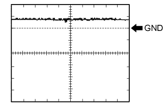 |
Waveform 4 (Reference)
| Item | Content |
| Tester Connection | D48-13 (EGIO) - D48-11 (GND) |
| Tool Setting | 2 V/DIV., 500 ms./DIV. |
| Condition | After cranking (after the engine speed reached at 500 r/min). |
| CHECK ID CODE BOX (IMMOBILISER CODE ECU) (w/ ID Code Box) |
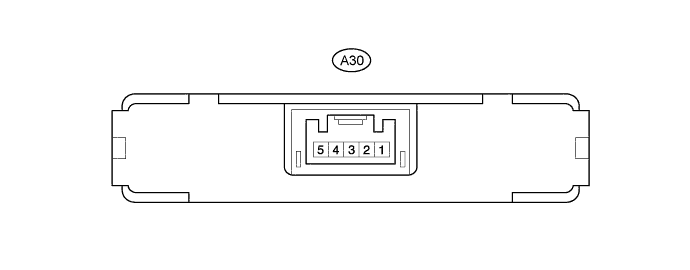
Disconnect the A30 ID code box (immobiliser code ECU) connector.
Measure the resistance and voltage according to the value(s) in the table below.
| Terminal No. (Symbol) | Input/Output | Wiring Color | Terminal Description | Condition | Specified Condition | Related Data List Item/DTC |
| A30-1 (+B) - A30-5 (GND) | Input | R-W - B-Y | +B power supply | Always | 11 to 14 V | - |
| A30-5 (GND) - Body ground | - | B-Y - Body ground | Ground | Always | Below 1 Ω | - |
Reconnect the A30 ID code box (immobiliser code ECU) connector.
Measure the voltage and check for pulses according to the value(s) in the table below.
| Terminal No. (Symbol) | Input/Output | Wiring Color | Terminal Description | Condition | Specified Condition | Related Data List Item/DTC |
| A30-4 (IMO1) - A30-5 (GND) | Input/Output | Y - B-Y | EFI communication signal (ID code box (immobiliser code ECU) to ECM) | Engine switch on (IG) | 11 to 14 V |
|
| EFI communication signal (ID code box (immobiliser code ECU) to ECM) | After cranking (after the engine speed reached at 500 r/min). | Pulse generation (See waveform 1) |
Inspect using an oscilloscope.
|
Waveform 1 (Reference)
| Item | Content |
| Tester Connection | A30-4 (IMO1) - A30-5 (GND) |
| Tool Setting | 2 V/DIV., 500 ms./DIV. |
| Condition | After cranking (after the engine speed reached at 500 r/min). |
| CHECK STEERING LOCK ACTUATOR ASSEMBLY (STEERING LOCK ECU) |
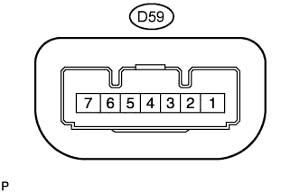 |
Measure the resistance and voltage and check for pulses according to the value(s) in the table below.
| Terminal No. (Symbol) | Input/Output | Wiring Color | Terminal Description | Condition | Specified Condition | Related Data List Item/DTC |
| D59-1 (GND) - Body ground | - | B - Body ground | Ground | Always | Below 1 Ω | - |
| D59-3 (SLR+) - Body ground | Input | Y - Body ground | Steering lock motor activation command signal (motor activation command signal sent from certification ECU (smart key ECU assembly)) | Any door opened when conditions below met, and then steering lock motor activated:
| Pulse generation (See waveform 1) |
|
| D59-4 (SLP) - Body ground | Output | LG - Body ground | Steering lock bar position signal (output signal from steering unlock sensor) | Steering locked → unlocked*3 | 11 to 14 V → Below 1.2 V |
|
| D59-6 (IGN1) - Body ground | Input | BR - Body ground | Power source mode signal (IG2 power supply input for entire steering lock actuator assembly) | Engine switch off → on (IG) | Below 1 V → 11 to 14 V |
|
| D59-7 (B) - Body ground | Input | SB - Body ground | Power source | Always | 11 to 14 V | B2788 |
Inspect using an oscilloscope.
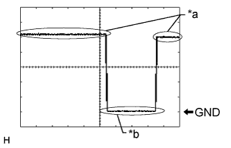 |
Waveform 1 (Reference)
| *a | Steering lock motor not operating |
| *b | Steering lock motor operating |
| Item | Content |
| Tester Connection | D59-3 (SLR+) - D59-1 (GND) |
| Tool Setting | 2 V/DIV., 200 ms./DIV. |
| Condition | Steering lock motor operates when both conditions met, and then door opened:
|
| CHECK ECM |
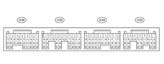
Measure the resistance and voltage and check for pulses according to the value(s) in the table below.
| Terminal No. (Symbol) | Input/Output | Wiring Color | Terminal Description | Condition | Specified Condition | Related Data List Item/DTC |
| A36-4 (E01) - Body ground | - | B-L - Body ground | Ground | Always | Below 1 Ω | - |
| A33-2 (BATT) - A36-4 (E01) | Input | W - B-L | +B power supply | Always | 11 to 14 V | - |
| A33-1 (+B2) - A36-4 (E01) | Input | V - B-L | +B power supply | Engine switch on (IG) | 11 to 14 V | - |
| A34-6 (+B) - A36-4 (E01) | Input | V - B-L | +B power supply | Engine switch on (IG) | 11 to 14 V | - |
| A35-25 (IMO) - A36-4 (E01) | Input | Y - B-L | ID code box (immobiliser code ECU)*1 or certification ECU (smart key ECU assembly) communication ID code box (immobiliser code ECU) communication input | Engine switch on (IG) | 11 to 14 V | - |
| After cranking (after the engine speed reached at 500 r/min). | Pulse generation (See waveform 1) | - |
Inspect using an oscilloscope.
|
Waveform 1 (Reference)
| Item | Content |
| Tester Connection | A35-25 (IMO) - A36-4 (E01) |
| Tool Setting | 2 V/DIV., 500 ms./DIV. |
| Condition | After cranking (after the engine speed reached at 500 r/min). |